
Fluid dynamic pressure bearing and production method for the same

a technology of dynamic pressure bearing and production method, which is applied in the direction of sliding contact bearings, shaft assemblies, mechanical equipment, etc., can solve the problems of limited rotation accuracy, high speed, and being able to produce little noise, and achieve the effect of rapid motor rotation start-up and long li

Inactive Publication Date: 2006-04-27
HITACHI POWDERED METALS COMPANY
View PDF17 Cites 12 Cited by
  • Summary
  • Abstract
  • Description
  • Claims
  • Application Information

AI Technical Summary

Benefits of technology

[0009] Therefore, an object of the present invention is to provide a fluid dynamic pressure bearing in which friction of the bearing and a shaft which easily occurs in start-up or in stopping of rotation of a motor can be prevented. An object of the present invention is to provide a fluid dynamic pressure bearing in which start-up of rotating a motor is thereby rapid. An object of the present invention is to provide a fluid dynamic pressure bearing of which lifetime increases. And an object of the present invention is to provide a production method for the above fluid dynamic pressure bearing.
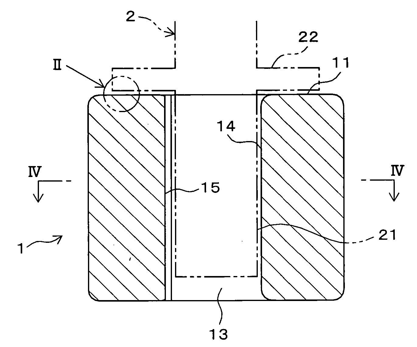
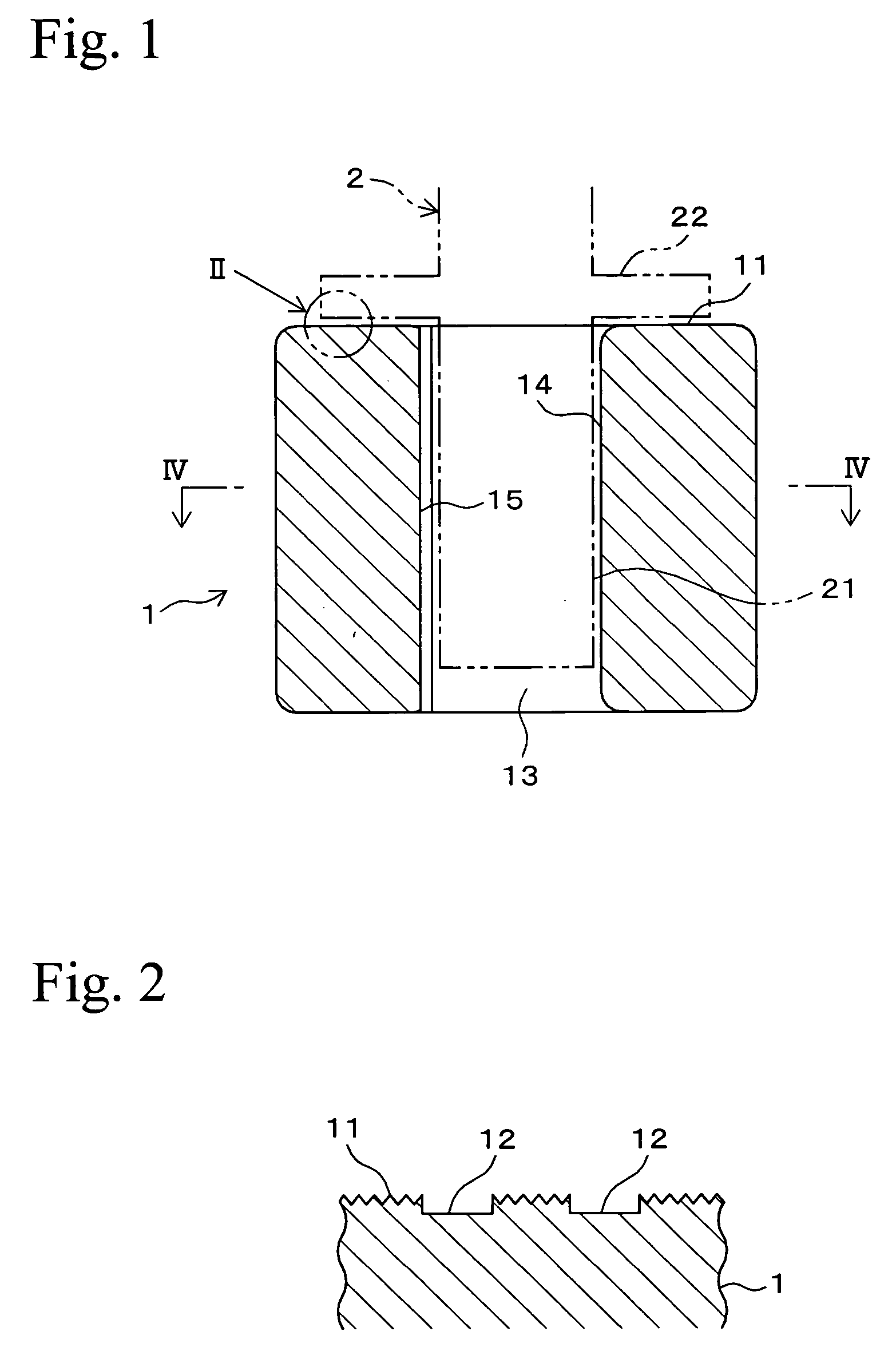
[0012] According to the above fluid dynamic pressure bearing of the present invention, a portion on the above thrust region other than the thrust recesses is formed to have the roughed portion having small peaks and valleys so as to be uneven. Lubricating oil is easily held in the valleys of the roughed portion which function as oil reservoirs. Therefore, in rotation start-up of or rotation stopping of the shaft, a large amount of the lubricating oil exists between the thrust region of the end surface and the thrust surface of the shaft, so that friction of the thrust region and the thrust surface is inhibited, and wear thereof is inhibited.
[0016] In the present invention, since the sintered bearing material (sintered compact) is a porous body, it is plastically deformed in the production of the sintered bearing. Therefore, the above transfer of the pattern of the roughed portion of the punch can be easily performed.
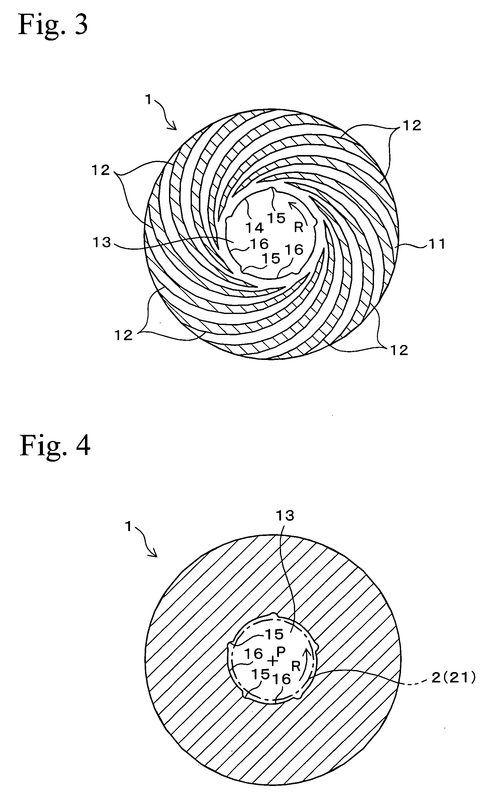
[0018] In production of the punch of another aspect of the present invention, formation of the protrusions on the punch surface and formation of the roughed portion on the surface (recesses on the punch surface) proximate to the protrusions can be simultaneously performed, so that the roughed portion can be formed on the recesses of the punch surface without increasing production processes. The roughed portion can be preferably small for making the thrust region be uneven, wherein the thrust region is on the end surface of the fluid dynamic pressure bearing. The end surface of the sintered bearing material can be pressed by the punch, so that formation of the thrust recesses and formation of the roughed portion on the thrust region of the end surface can be simultaneously performed. Therefore, the roughed portion can be formed on the end surface of the fluid dynamic pressure bearing without increasing production processes.
[0019] In the preferred embodiment of the present invention, although the protrusions on the punch surface of the punch are formed by electric discharge working or chemical etching, electric discharge working is preferably used. In the case in which the protrusions on the punch surface of the punch are formed by electric discharge working, the protrusions on the punch surface of the punch can be formed to have sharp edges, so that edges of the thrust recesses for generating thrust fluid dynamic pressure can be formed sharp by pressing the protrusions of the punch surface on the thrust region of the fluid dynamic pressure bearing. As a result, the thrust region of the fluid dynamic pressure bearing can have a desired shape.
[0021] According to one aspect of the fluid dynamic pressure bearing, the end surface receiving a thrust load is formed to have the roughed portion having small peaks and valleys so as to be even, so that the valleys of the roughed portion function as oil reservoirs. Therefore, in rotation start-up of or rotation stopping of the shaft, a large amount of the lubricating oil exists between the upper end surface and the shaft, and friction of the thrust region of the end surface and the thrust surface of the shaft is thereby inhibited. As a result, rotation start-up of the motor is rapid, and the fluid dynamic pressure bearing can have a long lifetime.

Problems solved by technology

In the above spindle motors, ball bearings were widely used as bearings, but they had limitations in rotation accuracy, high speed, and being able to produce little noise.
Therefore, in the case in which rotation speed of the motor is relatively low in start-up of the motor and in stopping of the motor, the supply amount of the lubricating oil is insufficient.
Due to this, friction of the shaft and the bearing is relatively large, so that metal contact easily occurs therebetween.
In particular, since a load on a thrust side is larger than that on a radial side, this problem is notably caused on the thrust side.
As a result, start-up of rotating the motor is slow, and lifetime of the fluid dynamic pressure bearing decreases.

Method used


Image

  • Fluid dynamic pressure bearing and production method for the same
  • Fluid dynamic pressure bearing and production method for the same
  • Fluid dynamic pressure bearing and production method for the same

Examples


examples

[0054] Next, examples of the present invention will be explained, and the effects of the present invention will be confirmed.

[0055] 49 mass % of Cu powder, 49 mass % of Fe powder, and 2 mass % of Sn powder were mixed into a raw powder, the raw powder was compacted into a green compact, and the green compact was sintered into a sintered compact, so that the required number of cylindrical sintered bearing materials was obtained. The sintered bearing materials had a density of 6.3 to 7.2 Mg / m3, an outside diameter of 6 mm, an inside diameter of 3 mm, and an axial direction length of 5 mm. Punches were produced by electronic discharge working so as to have punch surfaces having depth of 10 μm, wherein respective roughness of the punch surface was different from each other. The punches were repressed on end surfaces of the above sintered bearing materials. As a result, a roughed portion having small peaks and valleys was formed on bearing end surfaces which are thrust surfaces, and spir...


PUM

PropertyMeasurementUnit
Percent by massaaaaaaaaaa
Surface roughnessaaaaaaaaaa

Abstract

A fluid dynamic pressure bearing composed of a cylindrical sintered compact includes: a thrust region which is formed on an end surface of the bearing and receives at least a thrust load; a roughed portion having small peaks and valleys formed on the thrust region; and thrust recesses for generating thrust fluid dynamic pressure, which are formed on the thrust region.

Description

BACKGROUND OF THE INVENTION [0001] 1. Field of the Invention [0002] The present invention relates to a fluid dynamic pressure bearing which may be preferably used for spindle motors provided in recording disc drive devices, and relates to a production method for the fluid dynamic pressure bearing. [0003] 2. Description of Related Art [0004] For example, in various kinds of information devices such as disc drive devices which read and write information from and to a magnetic disc or an optical disc such a CD or a DVD, the above spindle motors are widely used as driving devices. In addition, in mirror drive devices such as laser printers, the above spindle motors are used as driving devices. In the above spindle motors, ball bearings were widely used as bearings, but they had limitations in rotation accuracy, high speed, and being able to produce little noise. Therefore, non-contact types of fluid dynamic pressure bearings which are superior in the above characteristics have been used...

Claims


Application Information

Patent Timeline
IPC IPC(8): F16C32/06
CPCF16C17/045F16C33/107F16C33/12F16C33/14F16C2204/60F16C2220/20F16C2223/04F16C2226/12
Inventor NII, KATSUTOSHISHIKATA, HIDEO
Owner HITACHI POWDERED METALS COMPANY
Learn More