Optical viewing system for monitoring a wide angle area of interest exposed to high temperature

a wide angle, monitoring system technology, applied in the direction of burners, combustion regulation, liquid fuel evaporation burners, etc., can solve the problems of local flow blockage, significant damage to turbine components, labor-intensive procedures, and high cos

Inactive Publication Date: 2006-04-27
SIEMENS POWER GENERATION
View PDF10 Cites 73 Cited by
  • Summary
  • Abstract
  • Description
  • Claims
  • Application Information

AI Technical Summary

Benefits of technology

[0008] The present invention provides an optical viewing system for the non-destructive monitoring of a high temperature area of interest with a confined space access, comprising an IR imaging device; an optical probe, having a shaft, a wide angle IR objective lens, and a relay optics unit; a cooling system adapted to cool the wide angle IR objective lens; and a processor that converts a detected image to a digital signal and display the digital signal on a visual monitor.

Problems solved by technology

However, these ceramic tiles have been known to detach from the inner wall and can enter the flow stream, become lodged in the first row vanes, resulting in local flow blockage.
This flow blockage may result in significant damage to turbine components downstream of the first row vanes.
Alternatively, in-situ visual inspections may be performed without engine disassembly by using a borescope inserted into a gas turbine engine, but such procedures are labor intensive, time consuming, costly, and require that the gas turbine engine be shut down.
However, each of these methods and apparatus has appreciable disadvantages.

Method used


Image

  • Optical viewing system for monitoring a wide angle area of interest exposed to high temperature
  • Optical viewing system for monitoring a wide angle area of interest exposed to high temperature
  • Optical viewing system for monitoring a wide angle area of interest exposed to high temperature

Examples


Embodiment Construction

Overview

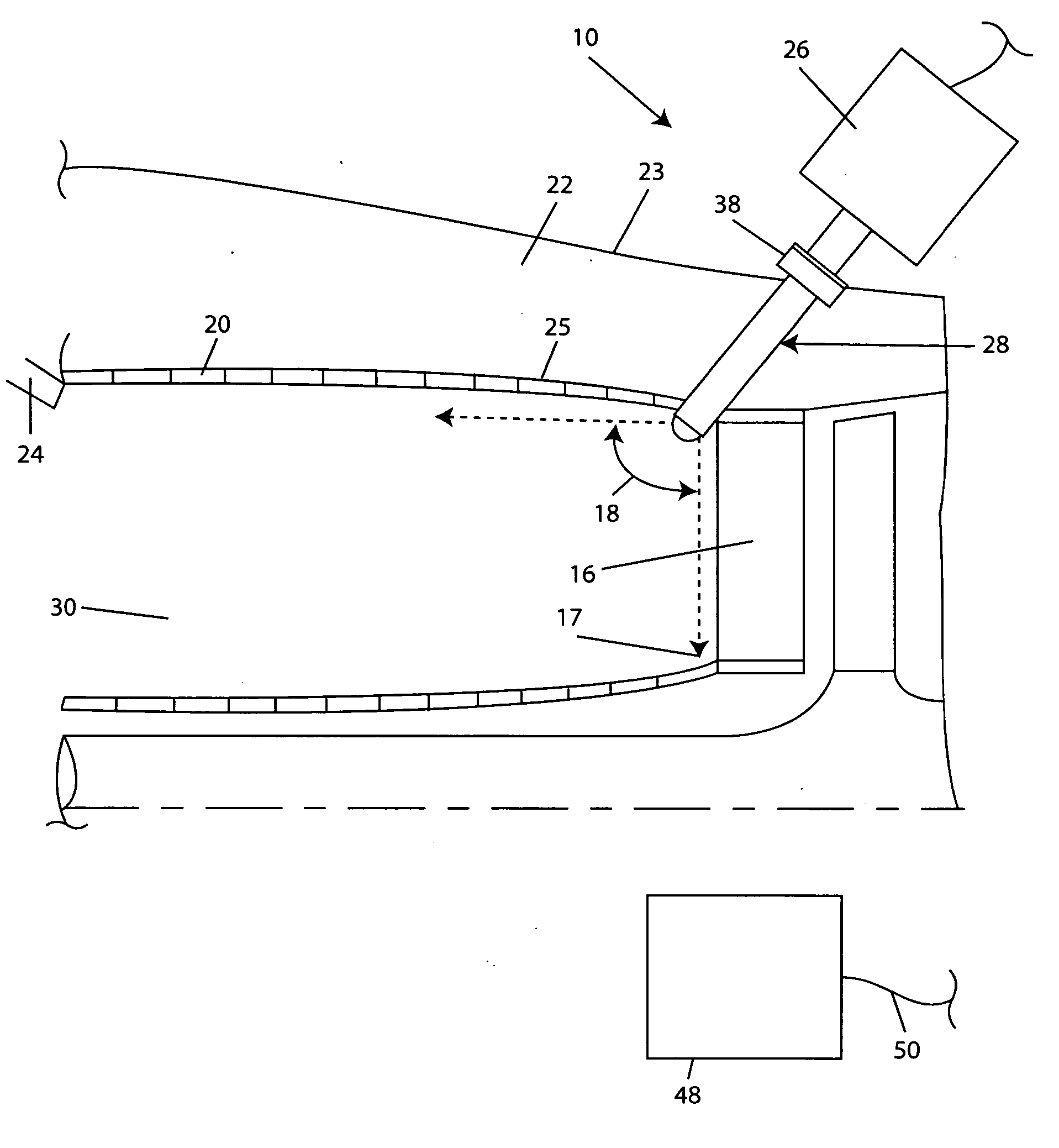
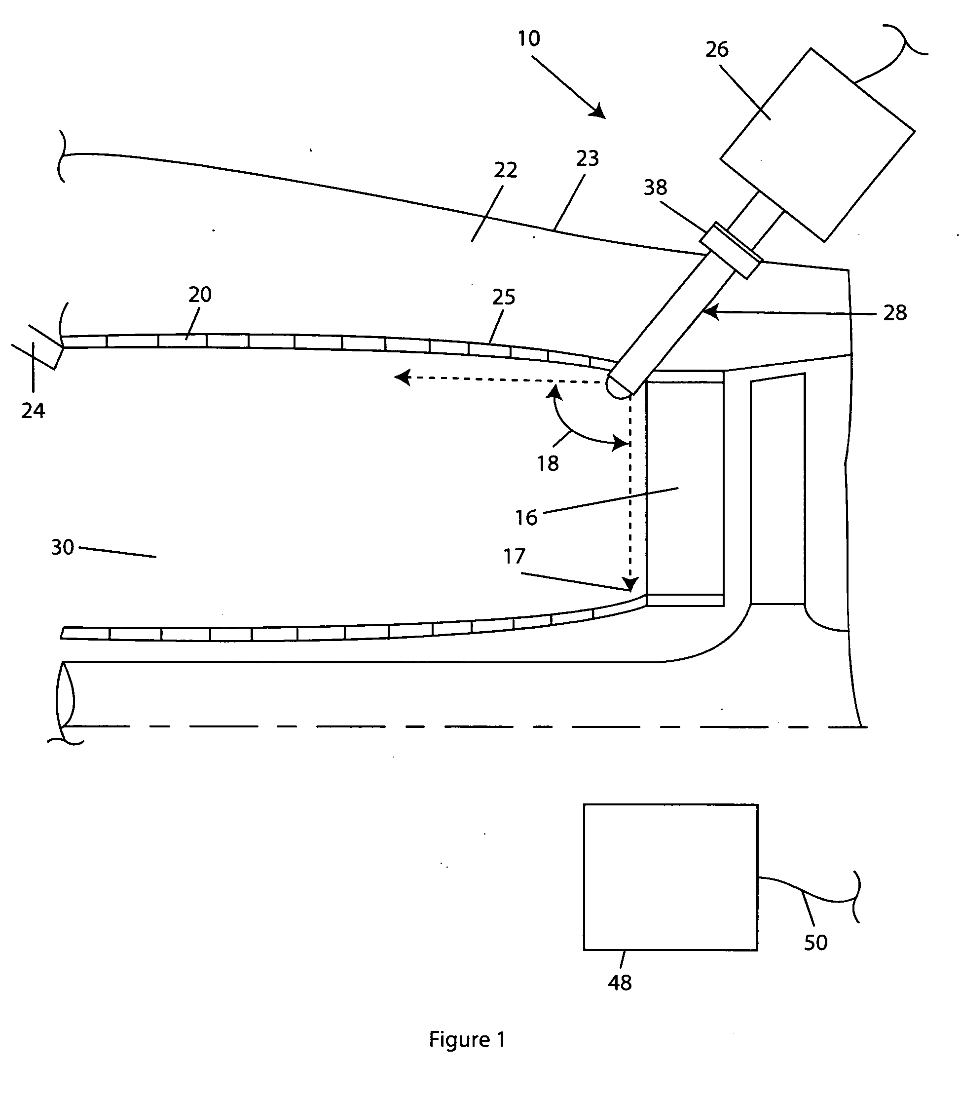
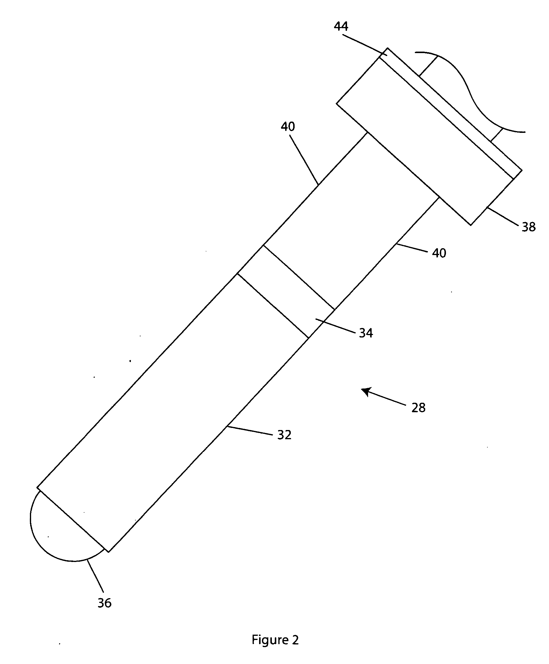
[0016] The invention described herein employs several basic concepts. For example, one concept relates a wide angle viewing system that is cooled by active cooling for use in a high temperature environment. Another concept relates a device and a method for monitoring ceramic tile integrity on the inner wall of an annular combustion chamber. Another concept relates to the monitoring of an area of interest where wide-angle viewing of a high temperature region through a confined access space is needed.

[0017] It is advantageous to define the term “area of interest” before describing the invention. “Area of interest” refers to any region where viewing or monitoring is desired. For example, the interface between the row 1 vane and the combustion chamber in an annular combustor in a gas turbine would be an area of interest.

[0018] The present invention is disclosed in context of use of a wide-angle infrared (IR) optical viewing system within a gas turbine engine for monitoring th...


PUM


Abstract

The present invention comprises a wide angle lens optical viewing system for the non-destructive monitoring of a high temperature area of interest with a confined space access, in particular, in a gas turbine engine. A novel cooling scheme is claimed that functions to cool the wide angle lens. Further, a method of monitoring an annular combustor region in the gas turbine via the optical viewing system is presented.

Description

FIELD OF THE INVENTION [0001] The present invention relates generally to optical based monitoring systems and, more particularly, to optical based monitoring systems for monitoring a high temperature, wide angle area of interest such as an annular combustion chamber. BACKGROUND OF THE INVENTION [0002] Gas turbine engines are known to include a compressor section, a combustor section, and a turbine section. Many components that form the turbine section, such as the stationary vanes, rotating blades and surrounding ring segments, are directly exposed to hot combustion gasses that can exceed 1500 C and travel at rotational velocities approaching the speed of sound. [0003] In some gas turbine engines, the combustion section is a 360° plenum, more commonly referred to as an annular combustor. Annular combustors typically have ceramic tiles arranged on the inner wall of the annular combustor to insulate the combustor cylinder from the hot, combusted gas. [0004] However, these ceramic tile...

Claims


Application Information

Patent Timeline
Patent Type & Authority Applications(United States)
IPC IPC(8): F23N5/08
CPCF23M11/045F23N5/082F23N2029/20F23N2229/20
Inventor BRUMMEL, HANS-GERDDIATZIKIS, EVANGELOS V.
Owner SIEMENS POWER GENERATION
Why Eureka
Try Eureka