Mounting structure of connector

a connector and mounting structure technology, applied in the direction of fixed connections, coupling device details, coupling device connections, etc., can solve the problems of difficult to satisfy the peeling strength of the circuit board, limited narrowed pitch between the terminals of the connector, and both cases have had problems

Inactive Publication Date: 2006-04-27
SONY CORP +1
View PDF8 Cites 43 Cited by
  • Summary
  • Abstract
  • Description
  • Claims
  • Application Information

AI Technical Summary

Benefits of technology

[0026] By being supported in a floating state in this way, a positional error of the connector with respect to the board at mounting can be tolerated.

Problems solved by technology

Further, in the dip type, since the mounting hole must be provided in the circuit board, the narrowed pitch between the terminals of the connector is limited to a pitch where the mounting holes do not make contact with each other.
That is, in the surface mounting type, since only the tail part of the terminal is adhered to the surface of the circuit board by the solder, the contacting area is small, and it is difficult to satisfy the peeling strength from the circuit board.
In other words, when using the surface mounting type or using the dip type, both cases have had problems, which have been tolerated in the past.
On the other hand, when the dip type is used, the peeling strength is increased, but the pitch between the terminals becomes large.

Method used


Image

  • Mounting structure of connector
  • Mounting structure of connector
  • Mounting structure of connector

Examples


Embodiment Construction

[0033] A preferred embodiment of the present invention will be described with reference to the drawings.

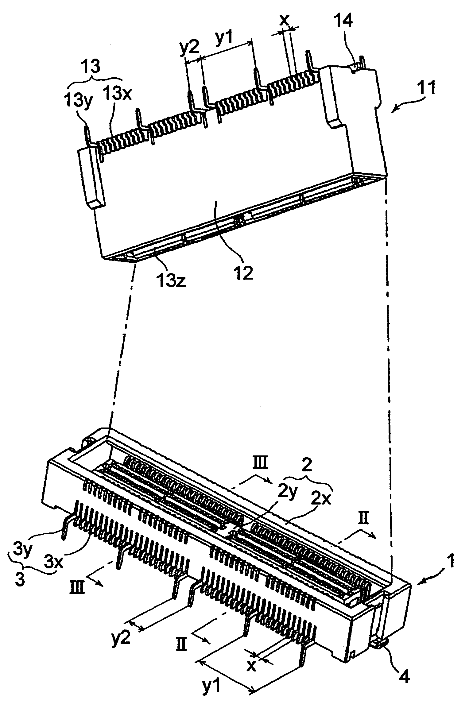
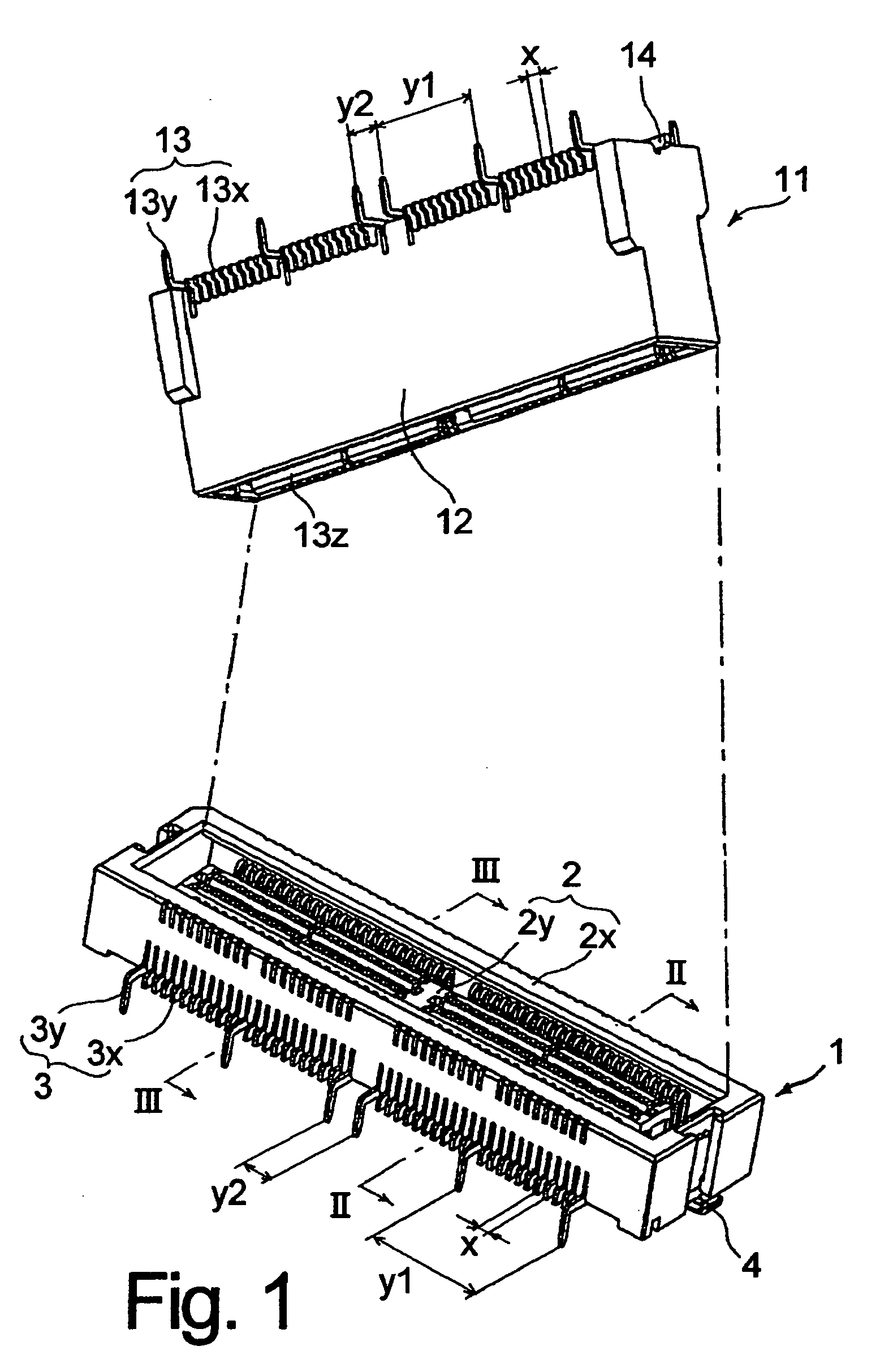
[0034]FIG. 1 illustrates an embodiment where the present invention is applied to a board-to-board type connector. This connector consists of a plug 11 mounted on one circuit board and a socket 1 mounted on the other circuit board. By fitting the plug 11 into the socket 1, both circuit boards are electrically connected.

[0035] First, the socket will be described using FIGS. 1, 2 and 3.

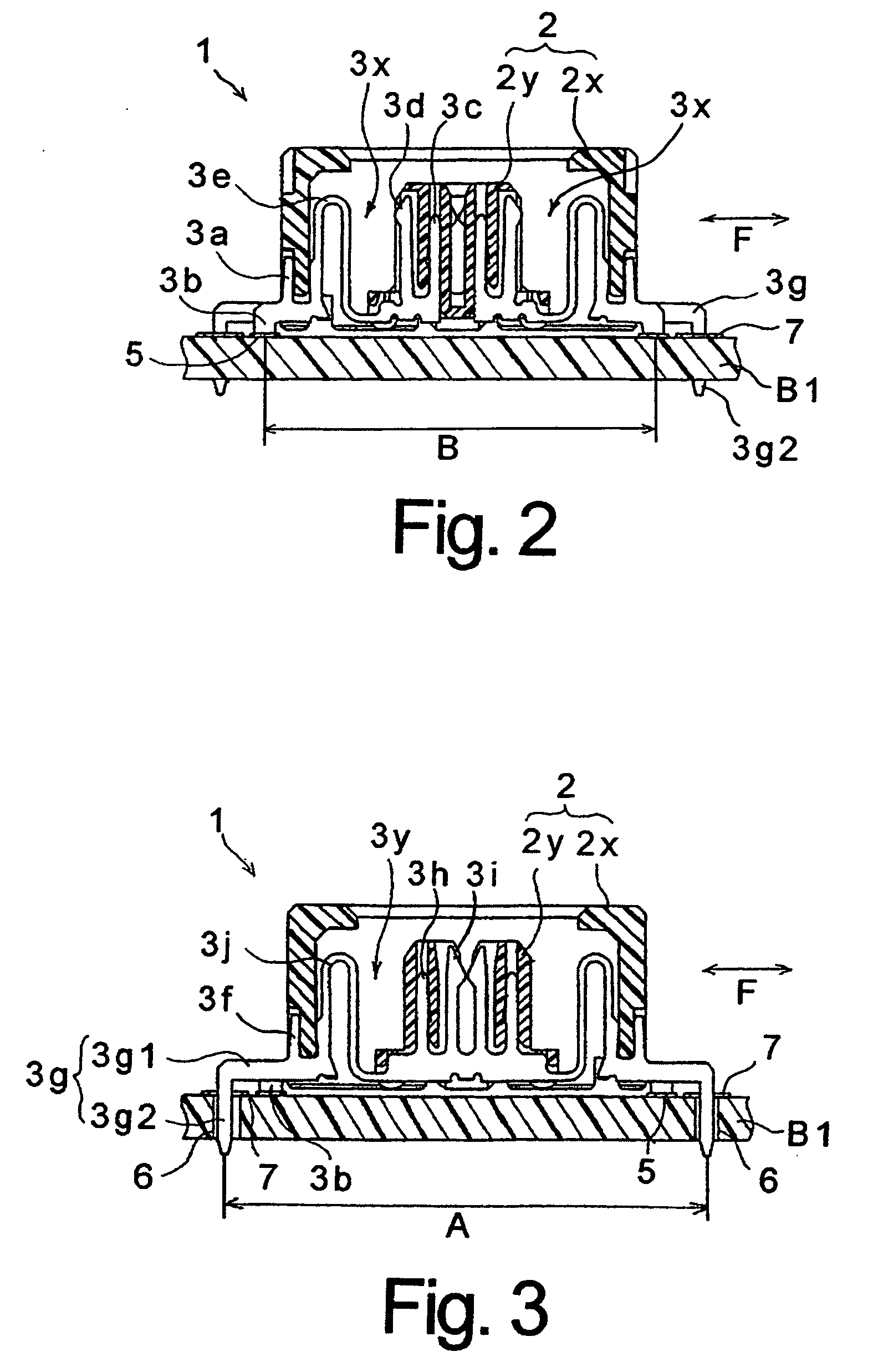
[0036] The socket 1 is to be mounted on a circuit board B1, and has a socket housing 2 as a connector housing, and a plurality of socket terminals 3 arranged in the socket housing 2. The socket housing 2 consists of an outside housing 2x formed to have a frame shape and an inside housing 2y arranged in an inner side of the outside housing 2x. The inside housing 2y is supported in the floating state with the outside housing 2x through the socket terminal 3.

[0037] The socket terminal 3 consists of a ...


PUM


Abstract

A connector mounting structure on a circuit board is presented. A connector has a plurality of terminals comprising a first terminal separated with a predetermined pitch and a second terminal separated with a pitch larger than the predetermined pitch. The first and second terminals have respectively a first tail part facing toward the circuit board and a second tail part bent on the circuit board side after extended in the lateral direction of the connector housing. The first tail part is reflow-soldered to a land part formed on the surface of the circuit board, and the bent top end of the second tail part is inserted into a mounting hole penetrating the other land part formed on the circuit board and reflow-soldered. In this mounting structure of the connector, it is simultaneously possible to narrow a pitch between terminals and to increase the peeling strength.

Description

DESCRIPTION OF RELATED APPLICATIONS [0001] The present application is based on the priority of Japanese Patent Application No. 2004-306861 (filed on 21, Oct. 2004) and the content of the above-described application is described in the specification of the present application. BACKGROUND OF THE INVENTION [0002] 1. Field of the Invention [0003] The present invention relates to a mounting structure for mounting a connector comprising a plurality of terminals on a circuit board, and more particularly, relates to a mounting structure of the connector capable of remarkably increasing peeling strength with respect to the circuit board while narrowing a pitch between the terminals. [0004] 2. Description of the Related Art [0005] A connector generally comprises a connector housing comprising insulating materials and a plurality of terminals, which are arranged in the connector housing and composed of electrically conductive materials. The connector is mounted on the circuit board by solderin...

Claims


Application Information

Patent Timeline
Patent Type & Authority Applications(United States)
IPC IPC(8): H01R12/00
CPCH01R12/57H01R12/58H01R23/688H01R12/716H01R12/91H01R13/6585H05K7/10
Inventor ORITA, KATSUYOSHIKAWAGUCHI, KEIJIMIYAJIMA, TAKASHITERUKI, SATORU
Owner SONY CORP
Why Eureka
Try Eureka