Method and apparatus for allocating a beacon signal in a wireless communications network

a wireless communication network and beacon technology, applied in the field of communication networks, can solve the problems of reducing the number of frequencies that can be used for caller traffic, reducing the number of co-channel interference, so as to improve spectral efficiency, improve spectral efficiency, and reduce adjacent channel interference and co-channel interference.

Inactive Publication Date: 2006-04-27
CINGULAR WIRELESS II LLC
View PDF7 Cites 81 Cited by
  • Summary
  • Abstract
  • Description
  • Claims
  • Application Information

AI Technical Summary

Benefits of technology

[0014] In accordance with the present invention, a method and apparatus are provided for transmitting beacon signals in a wireless communications network. For a given cell site, a single frequency may be used for the beacon signal by assigning different beacon signal time slots to different sectors of the cell site. During one time slot, the beacon signal is transmitted to one of the sectors, and during another one of the time slots, the beacon signal is transmitted to a different one of the sectors. Because a single frequency can be used for all of the sectors of a cell site, more frequencies are available for use for user traffic. Therefore, the invention improves spectr...

Problems solved by technology

As the number of frequencies used for the beacon signals increases, the possibility that co-channel interference will occur decreases.
However, increasing the number of frequencies that are reserved for the beacon signals decreases the number of frequencies that can be used for caller traffic.
Therefore, with the current beacon signal allocation scheme, a tradeoff exists between spectral efficiency and co-channel interference.
One of the disadvantages of allocating beacon signals in the manner described above with reference to FIGS. 1-3 is that a relatively large number of frequencies must be reserved for use as beacon signals, which reduces the spectral efficiency of the network.
Therefore, allocating a large number of frequencies for use as the beacon signals reduces the number of calls that can be handled by each cell site, thereby reducing network coverage and increasing overall network costs.
Another disadvantage of ...

Method used


Image

  • Method and apparatus for allocating a beacon signal in a wireless communications network
  • Method and apparatus for allocating a beacon signal in a wireless communications network
  • Method and apparatus for allocating a beacon signal in a wireless communications network

Examples


Embodiment Construction

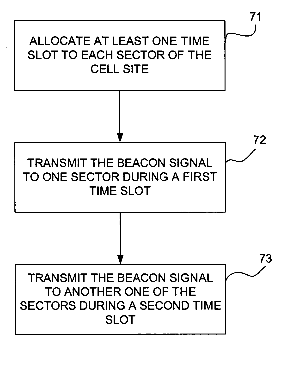
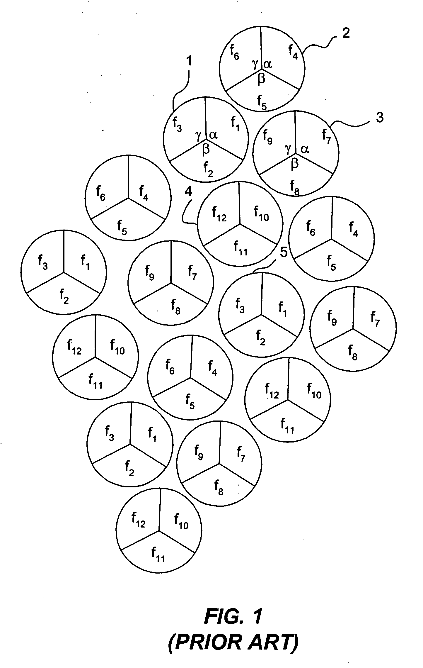
[0036] In accordance with the preferred embodiment of the present invention, a single frequency is allocated for the beacon signal for each cell site. FIG. 4 is a diagram of a plurality of cell sites, each of which is divided into three sectors, α, β and γ, with all of the sectors of a given cell site using the same frequency for the beacon signal for that site. This diagram represents an example of the manner in which frequencies can be allocated in accordance with the method of the invention. The beacon signal allocation configuration represented by the diagram shown in FIG. 4 is a 1 / 3 beacon signal frequency allocation scheme, where X=1 corresponds to the number of cell sites that use a given frequency for the beacon signal and Y=3 corresponds to the total number of frequencies used for the beacon signals for the network.

[0037] It should be noted that the invention is not limited to the 1 / 3 beacon signal frequency allocation scheme shown in FIG. 3. Other allocation schemes may b...


PUM


Abstract

A method and apparatus for transmitting beacon signals in a wireless communications network. For a given cell site, a single frequency may be used for the beacon signal by assigning different beacon signal time slots to different sectors of the cell site. During one time slot, the beacon signal is transmitted to one of the sectors, and during another one of the time slots, the beacon signal is transmitted to a different one of the sectors. Because a single frequency can be used for all of the sectors of a cell site, more frequencies are available for other purposes, such as for user traffic, for example. The invention improves spectral efficiency, reduces adjacent channel interference and co-channel interference and allows power consumption to be controlled.

Description

BACKGROUND OF THE INVENTION [0001] 1. Field of Invention [0002] The invention relates to communications networks and, more particularly, to a method and apparatus for allocating beacon signals in a communications network. [0003] 2. Description of Related Art [0004] In wireless communications networks, beacon signals, which are sometimes also referred to as pilot signals, are broadcast over the airwaves to enable mobile devices to search for cell sites that are handoff candidates. Generally, one beacon signal is required for each sector of each cell site and each beacon signal of a given cell site uses a different frequency. FIG. 1 is a diagram of a plurality of cell sites, each of which is divided into three sectors with each sector of a given cell site using a different frequency. The frequencies that are allocated for use as beacon signals for the network are frequencies f1 through f12. For cell site 1, which is shown in block diagram form in FIG. 2, the beacon signal for sector α...

Claims


Application Information

Patent Timeline
IPC IPC(8): H04Q7/20H04W16/02H04W16/24H04W48/12
CPCH04W16/02H04W16/24H04W48/12
Inventor HO, MING-JUJABBARY, ALIBARGHOUTHI, RAMZI
Owner CINGULAR WIRELESS II LLC
Why Eureka
Try Eureka