Antitheft system

a technology of anti-theft system and anti-theft device, which is applied in the direction of anti-theft device, process and machine control, program control, etc., can solve the problems of limiting the operation of both devices, affecting the safety of the system, so as to achieve the effect of suppressing the spread of damag

Inactive Publication Date: 2006-04-27
DENSO CORP
View PDF8 Cites 15 Cited by
  • Summary
  • Abstract
  • Description
  • Claims
  • Application Information

AI Technical Summary

Benefits of technology

[0059] When communication check operation function is installed in every device, the wire-harness connecting between those devices can also be modified to have a proprietary structure to accommodate a different number of signals and the like. In this manner, the proprietary structure of the wire-harness will appropriately prevent the vehicle 2 from stealing by deteriorating the motivation of theft, and spread of damage can also be suppressed when the onboard devices are removed from the vehicle 2 while it is being stolen.

Problems solved by technology

If the electrical connection, or ‘communication,’ is not checked, the anti-theft system either stops operation of both of itself and other devices, or limits operation of both of them.
Therefore, abnormality of connection between one of the onboard devices and the other devices will be detected if the object with onboard devices is stolen and any one of the onboard devices connected to each other is removed from the object.
This triggers either stopping of operation of the device and the other onboard devices, or alternatively enabling limited operation of the device and the other onboard devices, and causes the whole system as a group of devices not to work properly.
Furthermore, limited operation may be imposed only on the device itself that detected abnormality in communication check operation with other devices, or may be imposed only on the other devices.
As a result, either the not-removed devices stop to work, or not-removed devices limit their own operation, and the group of devices as a system will be prevented from working properly.

Method used


Image

  • Antitheft system
  • Antitheft system
  • Antitheft system

Examples


first embodiment

[0019] The first embodiment of the present invention, that is, an application of the present invention to a system comprising onboard devices, is described here with reference to FIG. 1 to FIG. 4. The first embodiment corresponds to the claim 1 to claim 3.

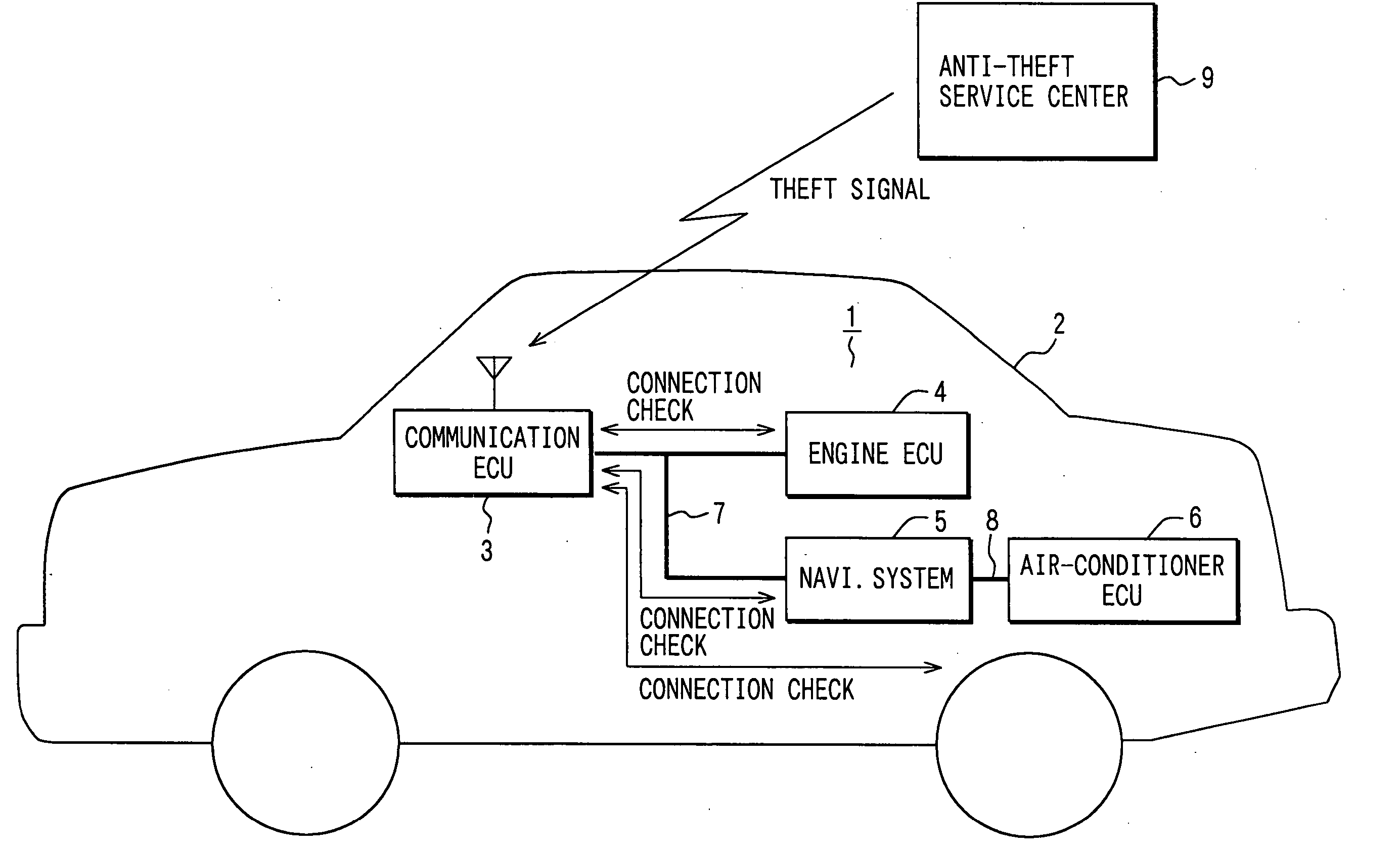
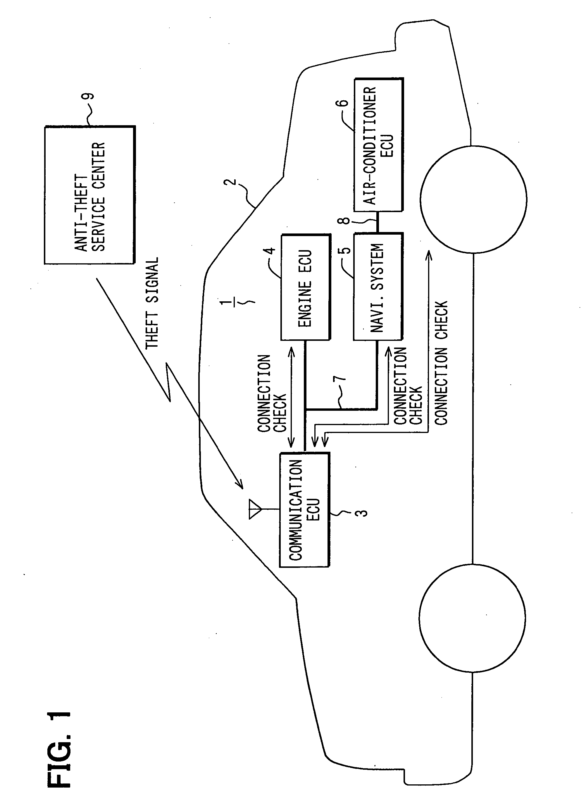
[0020]FIG. 1 shows a structural diagram of the entire system. The anti-theft system 1 comprises a communication ECU 3, an engine ECU 4, a car navigation system 5, and an air-conditioner ECU 6 connected each other on a vehicle 2 (an object with onboard devices in the present invention). A first communication line 7 connects the communication ECU 3, the engine ECU 4, and the car navigation system 5, and a second communication line 8 connects the car navigation system 5 and the air-conditioner ECU 6.

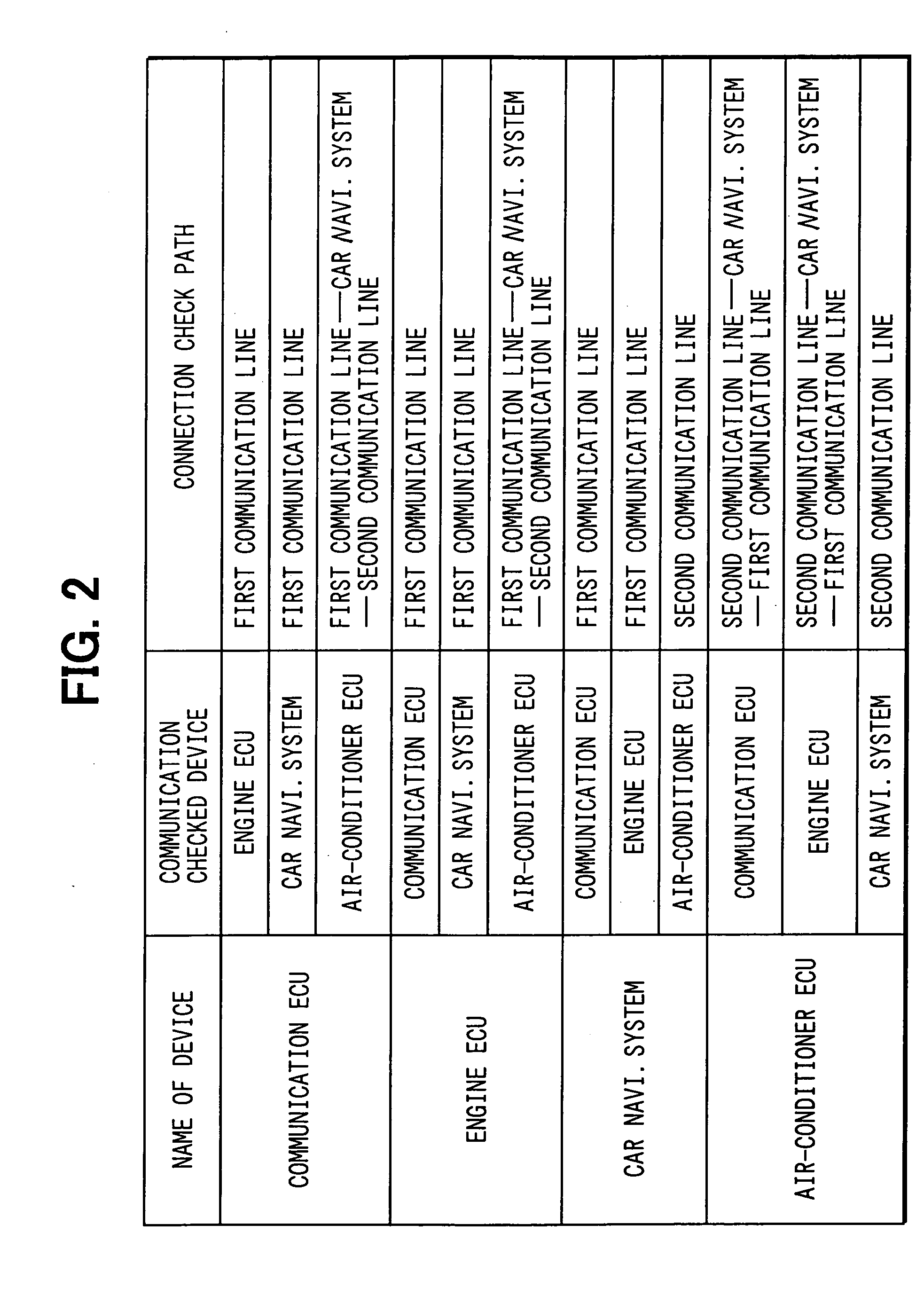
[0021] Each of those devices, that is, the communication ECU 3, the engine ECU 4, the car navigation system 5, and the air-conditioner ECU 6, checks an electrical connection, or ‘communication’ with other onboard devices. In this case, t...

second embodiment

[0039] Next, the second embodiment of the present invention is described with reference to the FIG. 5 and FIG. 6. In this description, the same portion as described in the first embodiment is omitted, and only the difference is described. The second embodiment corresponds to the claims 1, 4 and 11.

[0040] In the first embodiment, each of the following devices, that is, the communication ECU 3, the engine ECU 4, the car navigation system 5, and the air-conditioner ECU 6 is programmed to assure communication with other devices. In the second embodiment, the communication ECU 3 checks communication with the engine ECU 4, the car navigation system 5, and the air-conditioner ECU 6, and the communication check operation by the engine ECU 4, the car navigation system 5, and the air-conditioner ECU 6 is eliminated. In other words, the communication ECU 3 is programmed as a controlling device of the present invention.

[0041] In this scheme of operation, the communication ECU 3 determines in ...

third embodiment

[0055] Next, the third embodiment is described with reference to FIG. 7. The same portion as described in the second embodiment is eliminated and only the different portion is described. In the second embodiment, only the communication ECU 3 is checking the communication as a controlling device. In the third embodiment, the communication ECU 3 and the engine ECU 4 are regarded as controlling devices to assure communication.

[0056] In this case, both the communication ECU 3 and the engine ECU 4 will be controlling the car navigation system 5 and the air-conditioner ECU 6, and degree of restricted operation of the car navigation system 5 and the air-conditioner ECU 6 will be determined by a policy that a greater restriction overrides a smaller one. Therefore, the engine ECU 4 can work as a controlling device even when the communication ECU 3 cannot be used as a controlling device because of the revelation of the internal structure, and thus can prevent the onboard devices from operati...


PUM


Abstract

An object of the invention is to provide a theft prevention system that appropriately protects a vehicle from being stolen. A communication ECU 3, an engine ECU 4, a car navigation system 5 and an air conditioner ECU 6, all installed on a vehicle 2, communicate each other to assure electrical connection, or ‘communication.’ When an abnormality is detected in terms of communication, both of the communicated device and the device that conducts communication check operation stop to work. If any one of the above devices is removed from the vehicle 2 while the vehicle 2 is stolen, this scheme of operation prevents the onboard devices from working correctly as a total system. Therefore, the scheme of operation greatly decreases motivation of theft, resulting in protecting the vehicle 2 appropriately from theft.

Description

TECHNICAL FIELD [0001] The present invention relates to an anti-theft system that prevents an object with onboard devices connected each other, such as a vehicle and the like, from stealing. BACKGROUND ART [0002] It is widely known that there exists an apparatus that prevents a vehicle from stealing by not allowing an engine to work when a theft signal is received from an anti-theft service center (For example, JP-A-2002-59812). [0003] However, it can be foreseen that the apparatus using a prior art cannot appropriately enforce the expected functionality of preventing the vehicle from stealing when the apparatus itself is removed from the vehicle, that is, it cannot receive the theft signal from the anti-theft service center in order not to allow the engine to start. [0004] In view of the foregoing problem, the anti-theft system of the present invention is aimed at providing a system that appropriately prevents the object with onboard devices such as a vehicle from stealing by steep...

Claims


Application Information

Patent Timeline
Patent Type & Authority Applications(United States)
IPC IPC(8): G06F12/14H04N7/16G06F11/00G06F15/173B60Q1/00B60R25/24B60R25/04B60R25/10G08B15/00
CPCB60R25/20B60R25/00B60R25/10
Inventor OGISO, HARUHIKO
Owner DENSO CORP
Why Eureka
Try Eureka