

Electronic component
a technology of electronic components and components, applied in the direction of hybrid/edl capacitor protection/adjusting, capacitor terminals, hybrid capacitors, etc., can solve problems such as dielectric strength reduction, and achieve good solder wettability, good solder wettability, and reduced solder wettability
Active Publication Date: 2014-04-24
MURATA MFG CO LTD
View PDF2 Cites 0 Cited by
- Summary
- Abstract
- Description
- Claims
- Application Information
AI Technical Summary
Benefits of technology
The patent is about a method for improving the solder wettability of an external terminal member in semiconductor devices. By using a thin outer plating film made of gold, tin, or an alloy containing both, the method reduces the solder wettability in the periphery of the exposed portion of the terminal member, resulting in the suppression of solder spread and the prevention of damage to the insulating section during soldering. The method also includes the use of cracks in the thin region of the outer plating film to promote the oxidation of nickel and further enhance the reduction in solder wettability. Additionally, the method allows for a long interface distance between the external terminal member and the insulating section, resulting in low water permeability at the junction and reducing the likelihood of failure during soldering.
Problems solved by technology
The contact of the case 2 with the high-temperature melted solder 7 may possibly cause such a failure that the case 2 is partly melted or a crack 8 is formed in the case 2.
In the electronic component 3, in which the case 2 contains a capacitor element and an organic electrolyte solution and the entry of water from outside is strictly inhibited like, for example, an electric double-layer capacitor containing an organic electrolyte solution, the presence of the crack 8 may possibly cause a problem such as a reduction in dielectric strength.
Method used
View moreImage
Smart ImageViewing Examples

Examples
examples
[0058]Examples performed in order to confirm an effect due to the present invention are described below.
[0059]1. Preparation of Samples
example
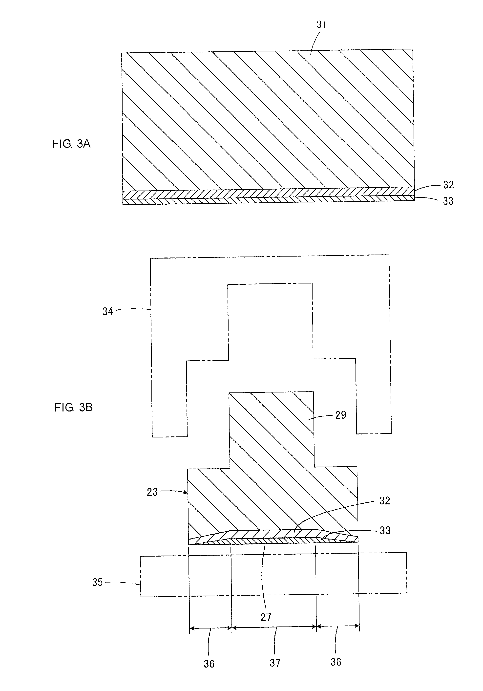
[0060]Aluminum plates with a thickness of about 0.5 mm were prepared. After being subjected to zincate treatment, a matte nickel plating film, serving as a base plating film, having a thickness of about 0.66 μm was formed on a principal surface of each aluminum plate. A gold plating film, serving as an outer plating film, having a thickness of about 0.15 μm was formed on the matte nickel plating film. Thereafter, press forming described with reference to FIGS. 3A and 3B and the like were performed, whereby an external terminal member according to an example was obtained.
Login to View More PUM
 Abstract
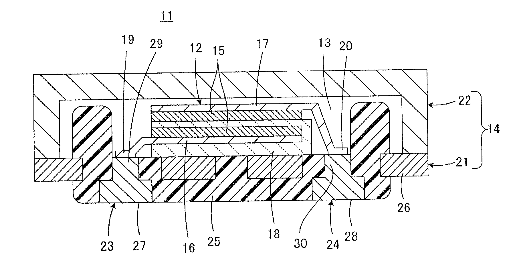
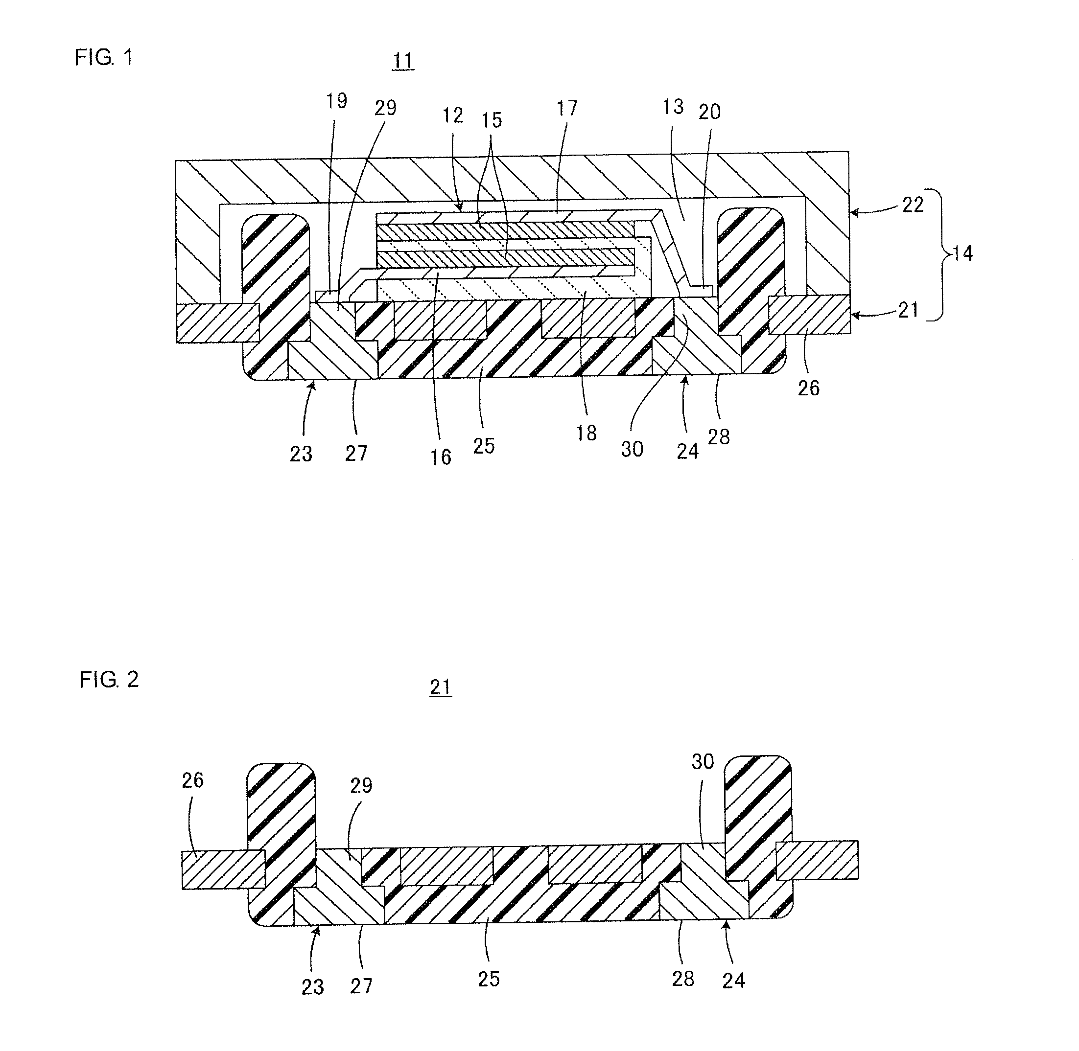
An electronic component includes an external terminal member made of a conductive metal and an insulating section in contact with the external terminal member. The external terminal member includes an exposed portion which faces outside and which is located on the predetermined surface side thereof. The electronic component is fixed with solder applied to the exposed portion of the external terminal member. The exposed portion of the external terminal member is given by a base plating film made of nickel or a nickel alloy and an outer plating film which is placed on the base plating film and which is made of gold, tin, or an alloy containing at least one of gold and tin. The outer plating film includes a relatively thick region and a relatively thin region surrounding the relatively thick region.
Description
CROSS REFERENCE TO RELATED APPLICATION[0001]The present application claims priority to Japanese Patent Application No. 2012-234302, filed Oct. 24, 1012, the entire contents of which are incorporated herein by reference.FIELD OF THE INVENTION[0002]The present invention relates to electronic components. The present invention particularly relates to an electronic component which includes an insulating section that is electrically insulating and also includes an external terminal member embedded in the insulating section, the electronic component being fixed with solder applied to the external terminal member.BACKGROUND OF THE INVENTION[0003]Japanese Unexamined Patent Application Publication No. 2011-100998 (hereinafter referred to as Patent Document 1) discloses a technique that is of interest to the present invention. In particular, FIGS. 1, 3A, and 3B in Patent Document 1 show a case, including a concave body and a lid, for electric double-layer capacitors. The case is made of resin ...
Claims
Login to View More Application Information
Patent Timeline
 Patent Type & AuthorityApplications(United States)
IPC IPC(8): H01G11/14
CPCH01G11/14H01G11/74H01G11/80H01G11/82Y02E60/13
InventorHARADA, HIROYUKIITAYA, MASAHARU
OwnerMURATA MFG CO LTD