
Semiconductor light emitting device having narrow radiation spectrum

a light-emitting device and semiconductor technology, applied in the field of semiconductor light-emitting devices, can solve the problems of restricting the use of light-emitting devices and the inability of light-emitting devices to be used in the field of visual light emission, and achieve the effect of suppressing the spread of radiation light-emitting spectrum

Active Publication Date: 2011-02-01
STANLEY ELECTRIC CO LTD
View PDF11 Cites 2 Cited by
  • Summary
  • Abstract
  • Description
  • Claims
  • Application Information

AI Technical Summary

Benefits of technology

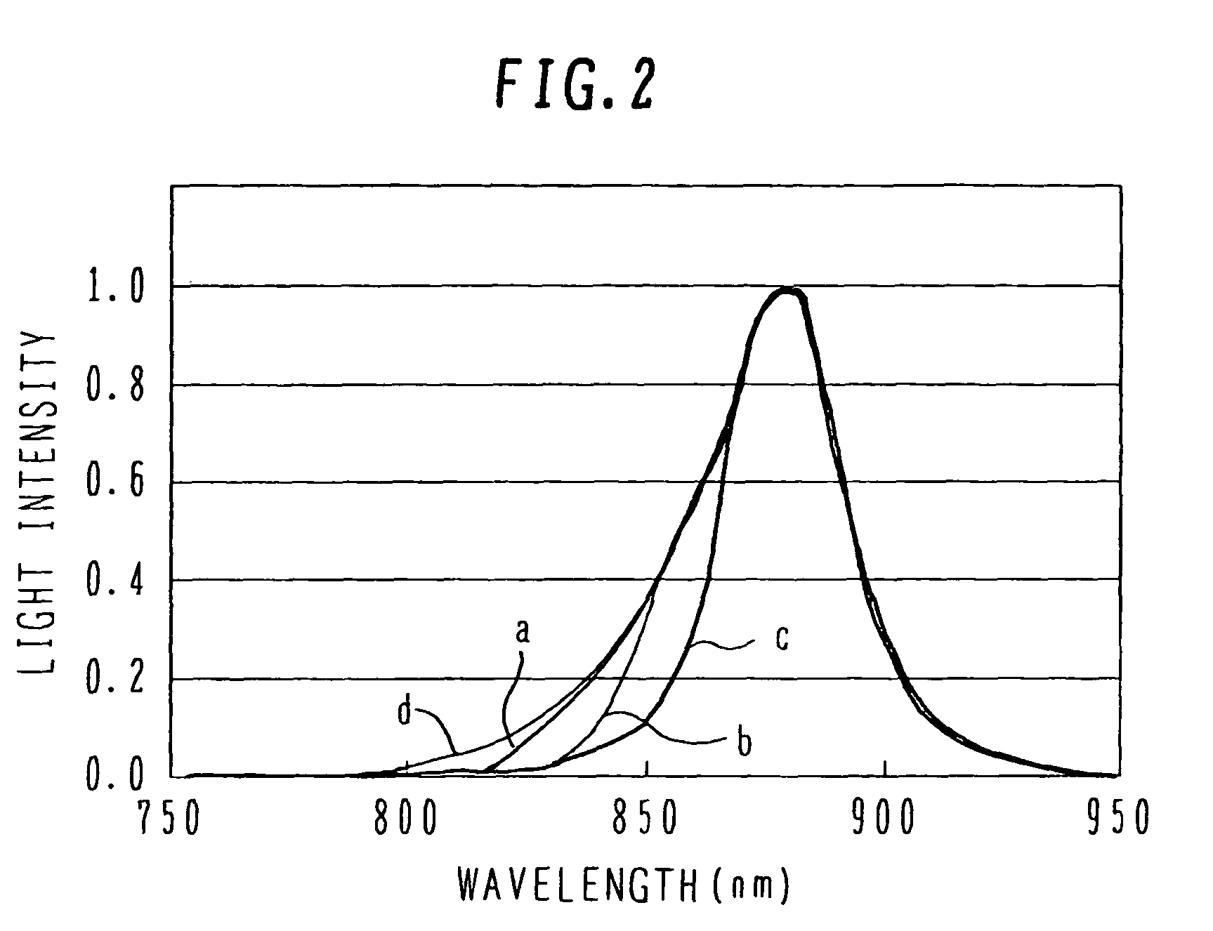
The present invention provides a semiconductor light emitting device that can narrow the spread of the spectrum of radiated light. This is achieved by using an active layer, a pair of clad layers, an optical absorption layer, and electrodes for injecting current into the active layer. The optical absorption layer has a wider band gap than the active layer and narrower band gap than the clad layer, which absorbs the light at the skirt of the spectrum. This results in a more focused light emission.

Problems solved by technology

If radiated light contains visual light, the usage of the light emitting device is restricted.
For example, this light emitting device cannot be used in the field prohibiting emission of visual light.

Method used


Image

  • Semiconductor light emitting device having narrow radiation spectrum
  • Semiconductor light emitting device having narrow radiation spectrum
  • Semiconductor light emitting device having narrow radiation spectrum

Examples


Embodiment Construction

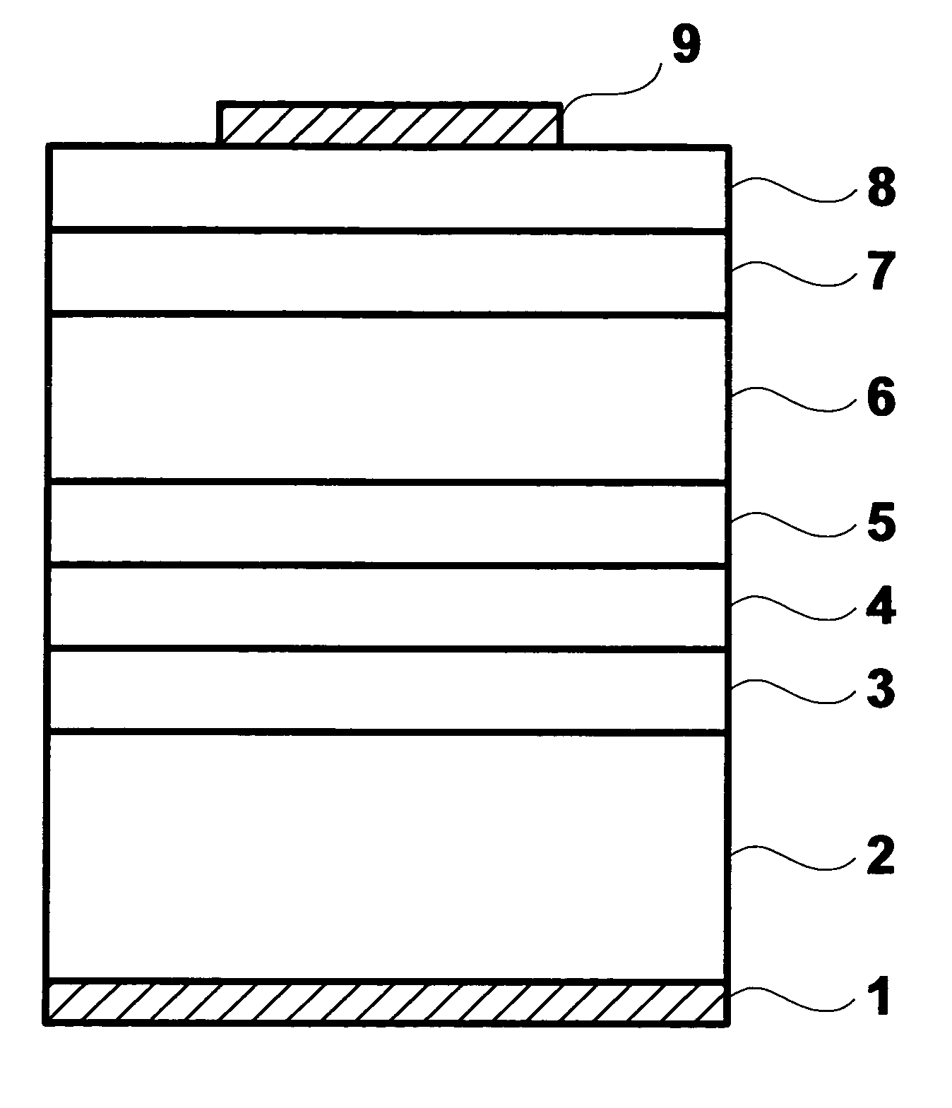
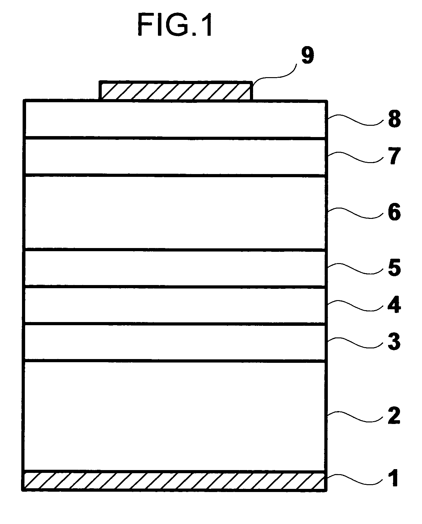
[0017]FIG. 1 is a schematic cross sectional view of a semiconductor light emitting device according to the first embodiment. On a principal surface of a semiconductor substrate 2 made of p-type GaAs, a lower clad layer 3, an active layer 4, an upper clad layer 5, a current spreading layer 6, an optical absorption layer 7 and a contact layer 8 are laminated in this order from the bottom.

[0018]The lower clad layer 3 is made of Zn- or Mg-doped p-type AlGaAs and has a thickness of 1 to 3 μm. A composition ratio of Al of the lower clad layer 3 is 0.3 to 0.4 and an impurity concentration is 1×1016 cm−3 to 1×1018 cm−3. The active layer 4 is made of p-type GaAs and has a thickness of 50 to 500 nm. An impurity concentration of the active layer 4 is 1×1017 cm−3 to 5×1018 cm−3.

[0019]The upper clad layer 5 is made of Si- or Se-doped n-type AlGaAs and has a thickness of 1 to 3 μm. A composition ratio of Al of the upper clad layer 5 is 0.3 to 0.4 and an impurity concentration is about 1×1018 cm−3...


PUM


Abstract

Radiation occurs when current is injected into an active layer from electrodes. A pair of clad layers is disposed sandwiching the active layer, the clad layer having a band gap wider than a band gap of the active layer. An optical absorption layer is disposed outside at least one clad layer of the pair of clad layers. The optical absorption layer has a band gap wider than the band gap of the active layer and narrower than the band gap of the clad layer. A spread of a spectrum of radiated light can be narrowed.

Description

CROSS REFERENCE TO RELATED APPLICATION[0001]This application is based on and claims priority of Japanese Patent Application No. 2004-292326 filed on Oct. 5, 2004, the entire contents of which are incorporated herein by reference.BACKGROUND OF THE INVENTION[0002]A) Field of the Invention[0003]The present invention relates to a semiconductor light emitting device, and more particularly to a semiconductor light emitting device capable of narrowing the spread of a spectrum of radiated light.[0004]B) Description of the Related Art[0005]An infrared light emitting device can be manufactured by using semiconductor material having a band gap in an infrared range. JP-A-2002-344013 discloses a light emitting device for infrared spatial optical communications, using an InGaAs strain quantum well layer as an active layer. This light emitting device has the InGaAs strain quantum well layer sandwiched by a pair of AlGaAs carrier confinement layers, and this lamination structure is sandwiched by a ...

Claims


Application Information

Patent Timeline
Patent Type & Authority Patents(United States)
IPC IPC(8): H01L29/06H01L33/00H01L31/00H01L33/06H01L33/14H01L33/30H01L33/40
CPCH01L33/02H01L33/44
Inventor SASAKURA, KENKAWAGUCHI, KEIZOONO, HANAKO
Owner STANLEY ELECTRIC CO LTD
Learn More