Hinge device

a technology of a hinge and a wing, which is applied in the field of hinge devices, can solve the problems of increasing the cost of manufacturing, limiting the reduction (miniaturization) of the axial size (length), and increasing the cost of machining, so as to reduce the number of parts, simplify the construction, and reduce the difficulty of assembly

Inactive Publication Date: 2006-05-04
NHK SPRING CO LTD
View PDF8 Cites 16 Cited by
  • Summary
  • Abstract
  • Description
  • Claims
  • Application Information

AI Technical Summary

Benefits of technology

[0035] (1) The leaf spring member, e.g. a spring washer doubles as a spring and two cam members used in the prior art, whereby one of the cam members becomes unnecessary, realizing a corresponding reduction in the number of parts and a simplified construction.
[0036] (2) The simplified construction involving a reduced number of parts makes the assembly easier and less troublesome, enabling a high-precision assembly process as well as an improv

Problems solved by technology

Although the above-described conventional hinge device proves satisfactory in proving such functions as opening/closing, stopping, and holding the display device (cover member), the conventional hinge device involves such problems as requiring a large number of parts and a complicated structure.
For this reason, the manufacture of such a conventiona

Method used


Image

  • Hinge device
  • Hinge device
  • Hinge device

Examples


first embodiment

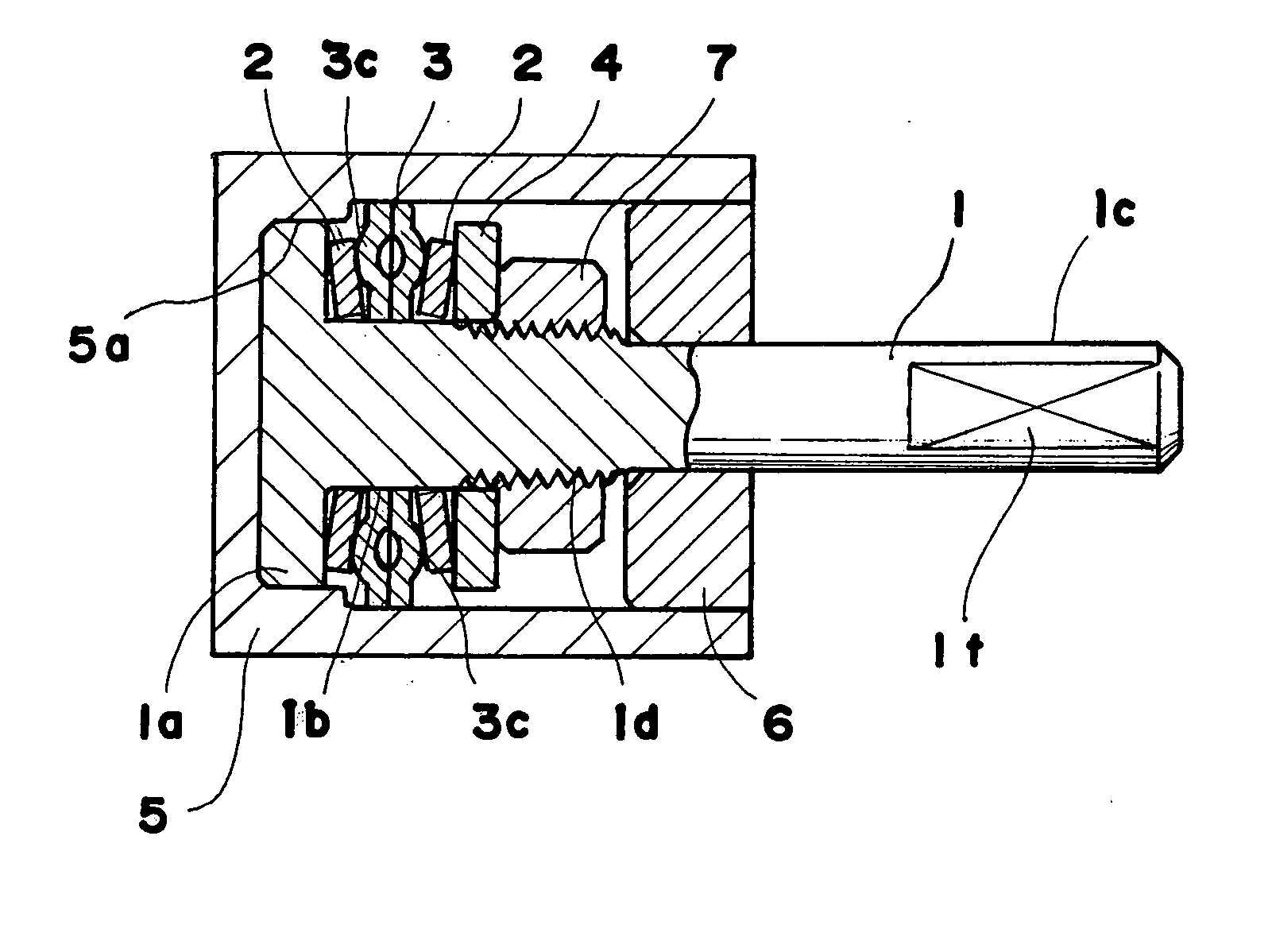
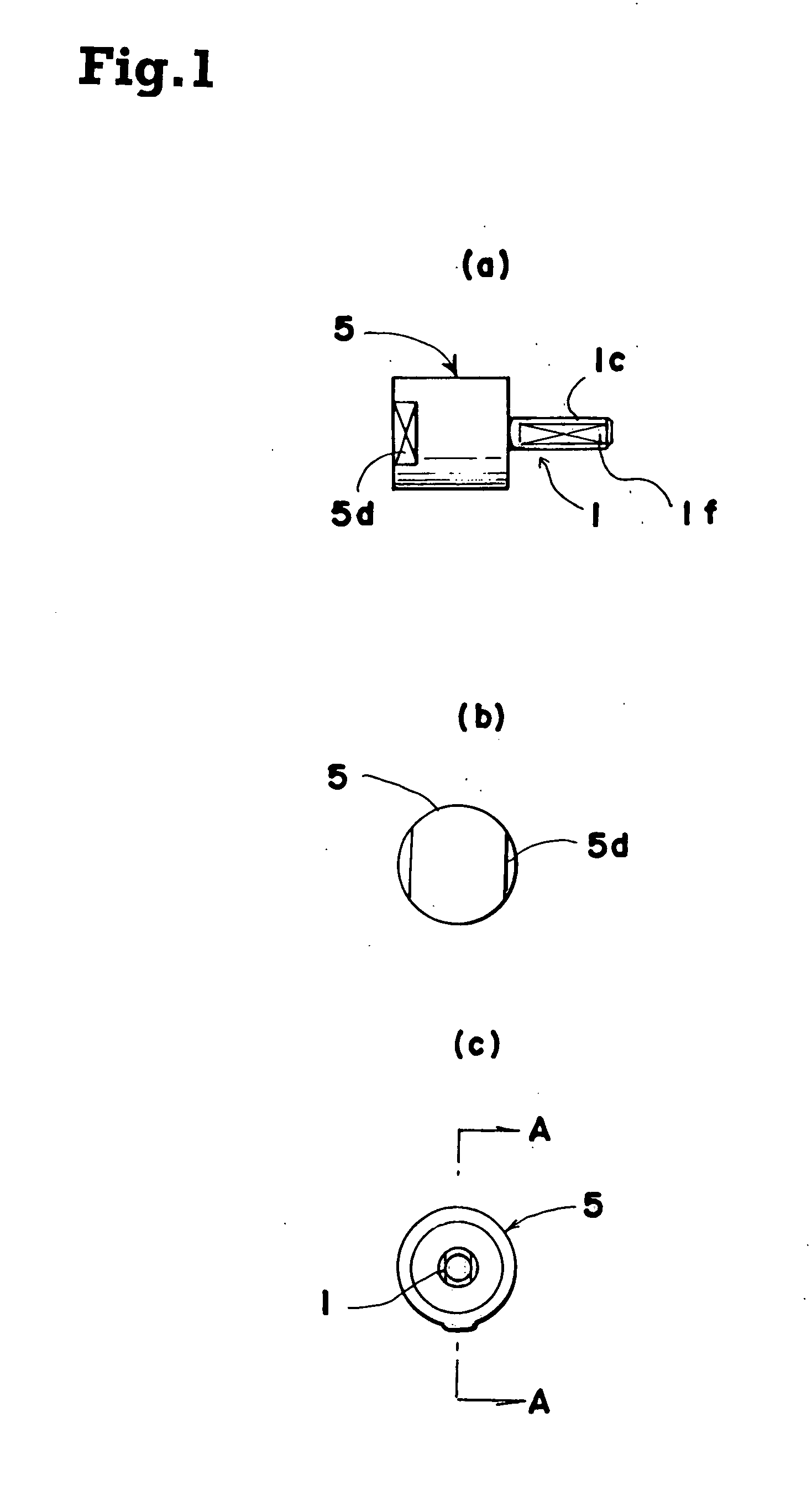
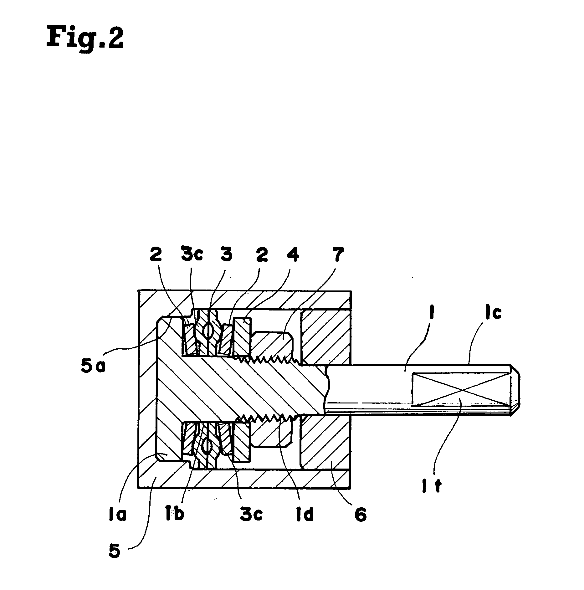
[0061] FIGS. 1 show a hinge device according to the present invention, of which FIG. 1(a) is a front view, FIG. 1(b) is a left-hand side view, and FIG. 1(c) is a right-hand side view, and FIG. 2 is an enlarged sectional view taken along the line A-A of FIG. 1(c).

[0062] This hinge device is composed of: a case 5 as a base member fixed to one member, for example, a main body; a movable shaft 1 rotatably mounted to the case 5 and to which the other member, for example, a cover member, is fixed; spring washers 2 each serving as a leaf spring member to be inserted onto the movable shaft 1 so as to be axially movable while having its rotation restricted (prohibited); and fixing plates 3 held in contact with the spring washers 2 and rotatably and axially movably inserted onto the movable shaft 1 while having their rotation restricted by the case 5. The spring washers 2 and the fixing plates 3 are held in press contact with each other while having their axial movement regulated by a presser...

seventh embodiment

[0090]FIG. 21 is an enlarged sectional view showing the present invention. In this embodiment, instead of the case 5 as described in the foregoing embodiments, a bracket 10 is used as the base member. The major feature of this embodiment resides in that a part of the bracket 10 also serves as the fixing plate 3.

[0091] That is, the bracket 10 is the one member, for example, a member to be fixed to the main body, with the movable shaft 1 being rotatably supported to the bracket 10. The movable shaft 1 is composed of the flange portion 1a, the main shaft portion 1b, and the support shaft portion 1c. A friction washer 11, the bracket 10, the spring washer 2, and the presser washer 4 are inserted onto the main shaft portion 1b. An end portion of the main shaft portion 1b is secured by caulking 1d to prevent dislodging, and presses the bracket 10 and the friction washer 11 through the intermediation of the spring washer 2. The main shaft portion 1b has a non-circular sectional configurati...

eleventh embodiment

[0107]FIGS. 34 and 35 each show a modification of the spring washer 2. FIG. 34 shows the spring washer 2 having cutouts 2d, and FIG. 35 shows the same having holes 2e. FIG. 36 shows a modification of the fixing plate 3, illustrating the fixing plate 3 having projecting portions 3f in addition to the cutout 3d. A rotation torque different from that of the eleventh embodiment can be attained by modifying the spring washer 2 and the fixing plate 3 into the spring washer 2 as shown in FIG. 34 or 35 and the fixing plate 3 as shown in FIG. 36, respectively. This may be achieved by changing the configurations of the spring washer 2 and fixing plate 3 as appropriate according to the rotation torque characteristics required.

[0108] It is to be noted that the construction for producing a clicking sensation according to this embodiment may be employed for the first through tenth embodiments as well.

[0109]FIG. 37 is an enlarged front view showing a twelfth embodiment of the present invention, a...


PUM


Abstract

Disclosed is a hinge device for openably and closably connecting one member and the other member, including: a base member fixed to the one member; a movable shaft that is rotatably supported by the base member and to which the other member is fixed; a leaf spring member having a curved portion and non-rotatably but axially movably inserted onto the movable shaft; and a fixing plate inserted onto the movable shaft such that the fixing plate does not rotate when the movable shaft rotates but is axially movable, the fixing plate having at least two protrusions provided on its surface in contact with the leaf spring member. The leaf spring member and the fixing plate are pressed into contact with each other for relative rotation therebetween.

Description

TECHNICAL FIELD [0001] This invention relates to a hinge device for openably and closably connecting two members like a main body and a cover member, for use in small OS devices or portable terminal devices, such as a notebook PC and a portable telephone, and toilet lids. BACKGROUND ART [0002] Information devices such as a notebook PC and a portable telephone have a keyboard provided in, for example, a main body thereof and have a display device provided in, for example, a cover member thereof. The cover member provided with the display device is connected to the main body through a hinge device, allowing the cover member to be opened / closed, stopped in position, and held at an angle for easy viewing. [0003] Conventionally, as disclosed in JP 10-252739 A, JP 11-44142 A, and the like, generally employed as such a hinge device is one having a pair of cams whose axes are in alignment with each other and which are capable of rotating relative to and moving toward and away from each othe...

Claims


Application Information

Patent Timeline
IPC IPC(8): E05D11/08F16F1/32G06F1/16
CPCE05D11/087E05Y2900/606F16F1/32Y10T16/5403G06F1/1679G06F1/1681G06F1/1616
Inventor KITAMURA
Owner NHK SPRING CO LTD
Why Eureka
Try Eureka