Production method of three-dimensional shape data of dental prosthesis

a three-dimensional shape and data technology, applied in the direction of mechanical measuring arrangements, impression caps, instruments, etc., can solve the problems of insufficient engagement of the implant fixture, remarkably difficult to correctly input the data, etc., and achieve the effect of improving the efficiency of the setting work of the automatic cutting machine and being easy to grasp

Inactive Publication Date: 2006-05-04
GC CORP
View PDF9 Cites 26 Cited by
  • Summary
  • Abstract
  • Description
  • Claims
  • Application Information

AI Technical Summary

Benefits of technology

[0040] Further, when the three-dimensional measuring device comprising the arithmetic process part is used, where the arithmetic process part is for arithmetic processing of the measured value of the three-dimensional coordinates of the shape of the measured object measured by the measuring part, the three-dimensional shape data of the dental prosthesis in various embodiments can be produced, so that it is preferable. Further, the three-dimensional shape data of the dental prosthesis can be subjected to various processing, so that it is preferable. Further, in the three-dimensional measuring device comprising such the arithmetic process part, when the arithmetic process part is for changing the three-dimensional coordinate of the shape other than the engaging portion of the model of the dental prosthesis, which uses Z axis as the reference, to the data for displaying the image of the computer, the image of the dental prosthesis to be produced can be easily grasped. Further, for example, when the data for displaying the image of the adjacent tooth or the like of the part applied with the dental prosthesis is also inputted to be displayed with the image of the dental prosthesis, the image of an occulussal surface or a contacting surface with the adjacent tooth of the dental prosthesis can be easily grasped. Thus, on the basis of this data, the produced three-dimensional shape data of the dental prosthesis can be corrected to have the suitable shape, so that it is preferable. Further, when the arithmetic process part is for changing the X and Y axes in the three dimensional coordinates of the shape other than that of the engaging portion using Z axis as the reference to the three-dimensional coordinate having new X and Y axes, where the pre-specified direction of the mounting part of the measured object mounting tool is orthogonally crossed with the Z axis and becomes a specified direction on the coordinates indicated by new X and Y axes having the origin at the cross point, for example, in the case of cutting the block for cutting the dental prosthesis provided in the automatic cutting machine, the data required by the automatic cutting machine in the three-dimensional measuring device is automatically produced, even when the relationship between the pre-specified direction of the three-dimensional shape data required by the automatic cutting machine and the X and Y axes and the relationship between the pre-specified direction of the mounting part of the measured object mounting tool of the three-dimensional coordinates measured by the three-dimensional measuring device and the X and Y axes are not conformed. Thus, the efficiency of the setting work of the automatic cutting machine can be improved. Furthermore, when the arithmetic process part is the part having the compensation function for compensating the line to the smooth continuous line, where the line is drawn on the basis of the three-dimensional coordinates of the shape other than the engaging portion of the model of the dental prosthesis using Z axis as the reference, the shape other than the engaging portion on the three-dimensional shape data becomes smooth. Thus, uncomfortable feeling can be made minimum when the produced dental prosthesis is fixed in the oral cavity, so that it is preferable.

Problems solved by technology

However, the following problem was found.
Thus, it is remarkably difficult to correctly input the data while grasping these relationships.
Further, since the dental prosthesis is interfered with the adjacent tooth when such the dental prosthesis is fixed at the implant fixture, the produced dental prosthesis cannot be sufficiently engaged with the implant fixture.

Method used


Image

  • Production method of three-dimensional shape data of dental prosthesis
  • Production method of three-dimensional shape data of dental prosthesis
  • Production method of three-dimensional shape data of dental prosthesis

Examples


Embodiment Construction

[0056] Hereinafter, the production method of the three-dimensional shape data of the dental prosthesis according to the present invention is concretely explained with drawings.

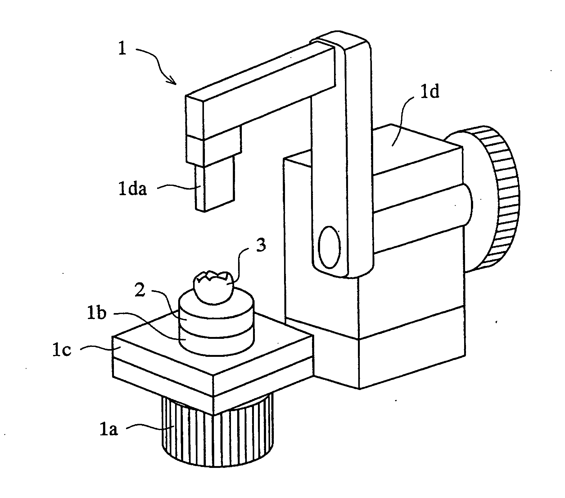
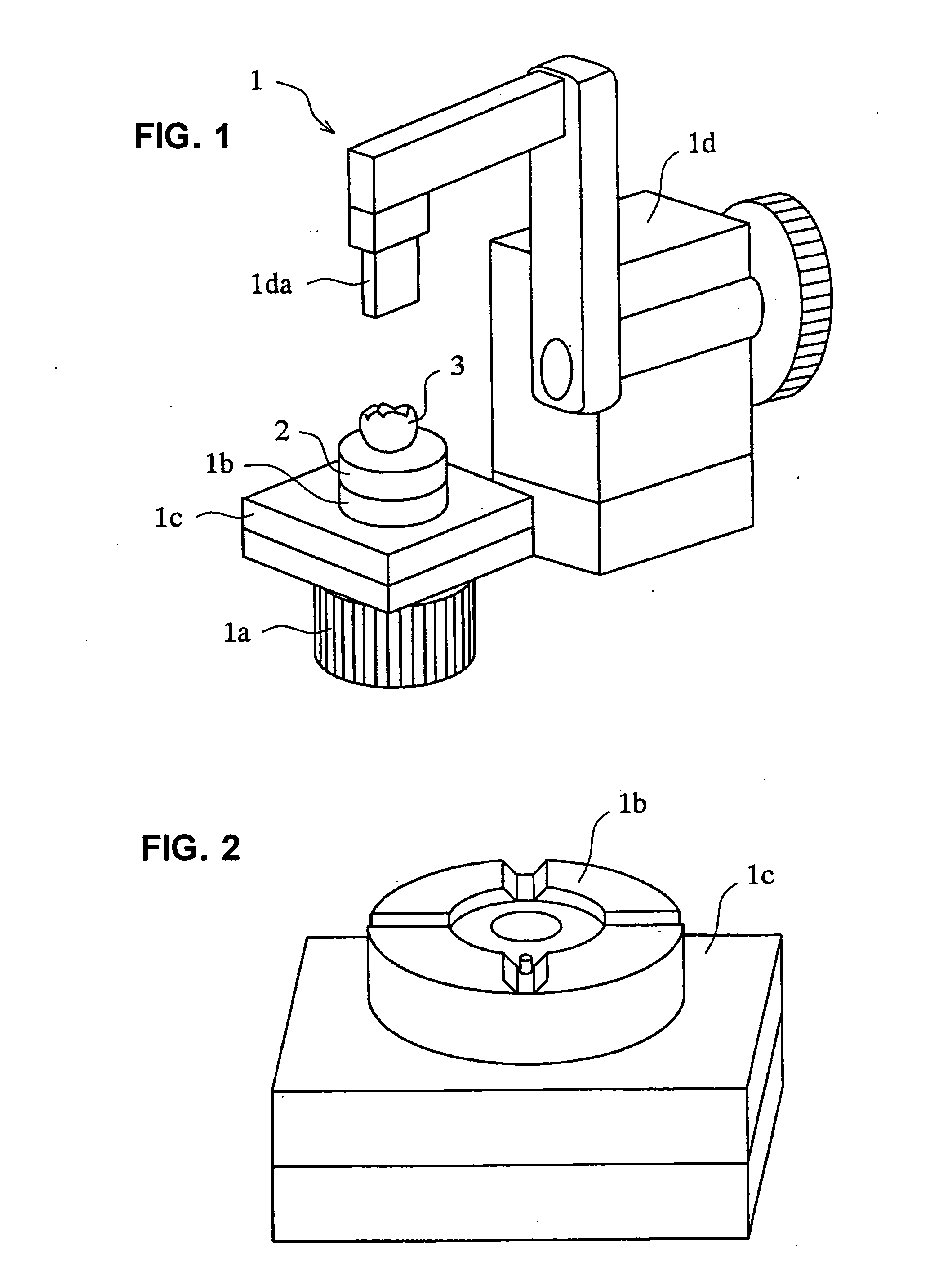
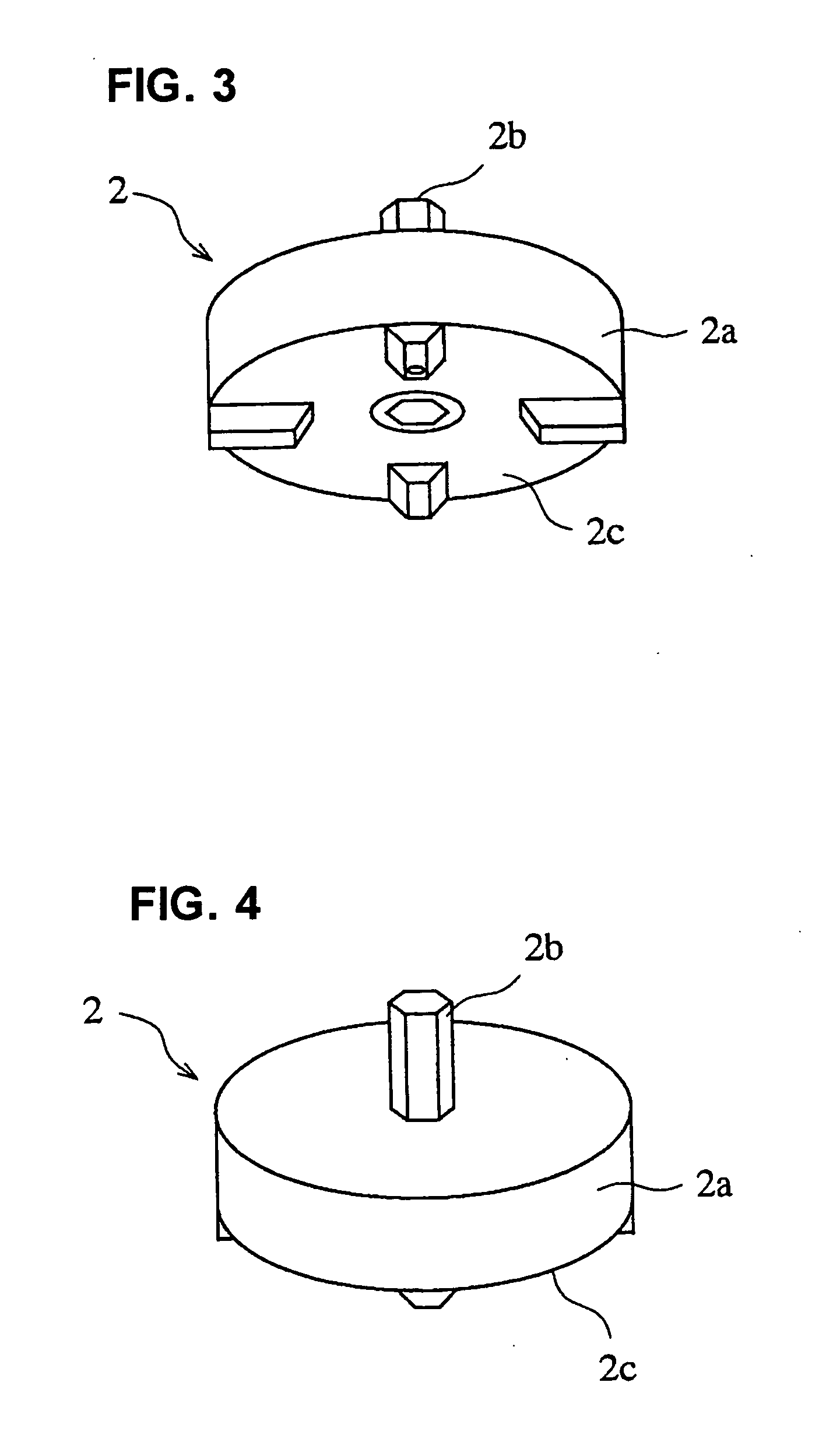
[0057]FIG. 1 is a perspective explanation view schematically illustrating one example of a three-dimensional measuring device used in the present invention. FIG. 2 is a perspective enlarged explanation view illustrating a shape of an upper part of a placing table in the state where a measured object mounting tool is removed from the placing table of the three-dimensional measuring device illustrated in FIG. 1. FIG. 3 is a perspective enlarged explanation view illustrating a lower part of the measured object mounting tool removed from the placing table of the three-dimensional measuring device illustrated in FIG. 1. FIG. 4 is a perspective enlarged explanation view illustrating an upper part of the measured object mounting tool removed from the placing table of the three-dimensional measuring device illustrate...


PUM


Abstract

To provide a production method of three-dimensional shape data of a part other than an engaging portion by a three-dimensional measuring device, the engaging portion has an engaging part in a cross sectional shape other than a rotary body and is projected and/or recessed on a jawbone side, a measured object mounting tool 2 comprises a cylindrical part 2a, a mounting part 2b and a placing part 2c, the mounting part 2b positions a prolonged line of an axis of the cylindrical part 2a in the engaging part 3aa, the placing part 2c aligns a pre-specified direction of the mounting part 2b with a specified providing direction of the placing table 1b, the center axis of the cylindrical part 2a is aligned with Z axis, and the model of the dental prosthesis 3 is rotated around Z axis on the basis of the specified providing direction of the placing table 1b.

Description

BACKGROUND OF THE INVENTION [0001] 1. Field of the Invention [0002] The present invention relates to a production method of three-dimensional data of a dental prosthesis for cutting a block for cutting the dental prosthesis by an automatic cutting machine by using a three-dimensional measuring device so as to have the same shape as a measured object. [0003] 2. Description of the Conventional Art [0004] As a general production method of the dental prosthesis such as an inlay, a crown, a bridge or the like, the following methods have been widely known. A method comprises casting of a metallic material by a lost wax casting method, to thereby produce the dental prosthesis. Another method comprises building up of a ceramics material on a refractory model, and baking of it in a vacuum electric furnace, to thereby produce the dental prosthesis for the purpose of aesthetic appreciation, such as a ceramic inlay, an all ceramic crown or the like. [0005] However, as for the work for producing...

Claims


Application Information

Patent Timeline
Patent Type & Authority Applications(United States)
IPC IPC(8): G01B5/004A61C19/04A61C5/77
CPCA61C9/004A61C13/0004G01B11/24A61C9/0093G16H20/40
Inventor MATSUDA, YOSHINORISAKAMOTO, YUUKIEBIHARA, YOSHINORI
Owner GC CORP
Why Eureka
Try Eureka