
Motion sensor and method for detecting motion

a motion sensor and motion technology, applied in the field of detecting motion, can solve the problems that the low cost sensor package using micro-electro-mechanical systems (mems) sensors has not provided the accuracy necessary for at least some of these applications

Active Publication Date: 2006-05-04
ARCHANGEL SYST
View PDF9 Cites 4 Cited by
  • Summary
  • Abstract
  • Description
  • Claims
  • Application Information

AI Technical Summary

Benefits of technology

[0004] Aspects of the invention provide a motion sensor that can detect movement of a body. Aspects of such movement that may be detected include linear and/or angular acceleration and/or angular velocity relative to one axis, two orthogonal axes or three orthogonal axes. In one aspect of the invention, movement of a body or reference structure may be detected relative to one or more spinning rotors. The rotor(s) may be suspended for rotation and/or other movement relative to the reference structure without physically contacting the reference structure. For example, the rotor(s) may be electrostatically suspended in a space in such a way that movement of the rotor(s) in the space relative to the reference structure may be detected without physical contact with the rotor(s). In one aspect of the invention, an electrical charge may be injected or otherwise pl

Problems solved by technology

Low cost sensor packages using Micro-Electro-Mechanical Systems (MEMS) sensors have not provided the accuracy necessary for at least some of these applications.

Method used


Image

  • Motion sensor and method for detecting motion
  • Motion sensor and method for detecting motion
  • Motion sensor and method for detecting motion

Examples


Embodiment Construction

[0015] Various aspects of the invention are described below with reference to illustrative embodiments. However, it should be understood that aspects of the invention are not limited to those embodiments described below, but instead may be used in any suitable system or arrangement. For example, an illustrative embodiment is described below in which a pair of counter-rotating rotors is used to detect movement. However, it should be understood that only a single rotor may be used, that two or more rotors may be used that rotate about non-parallel axes, etc.

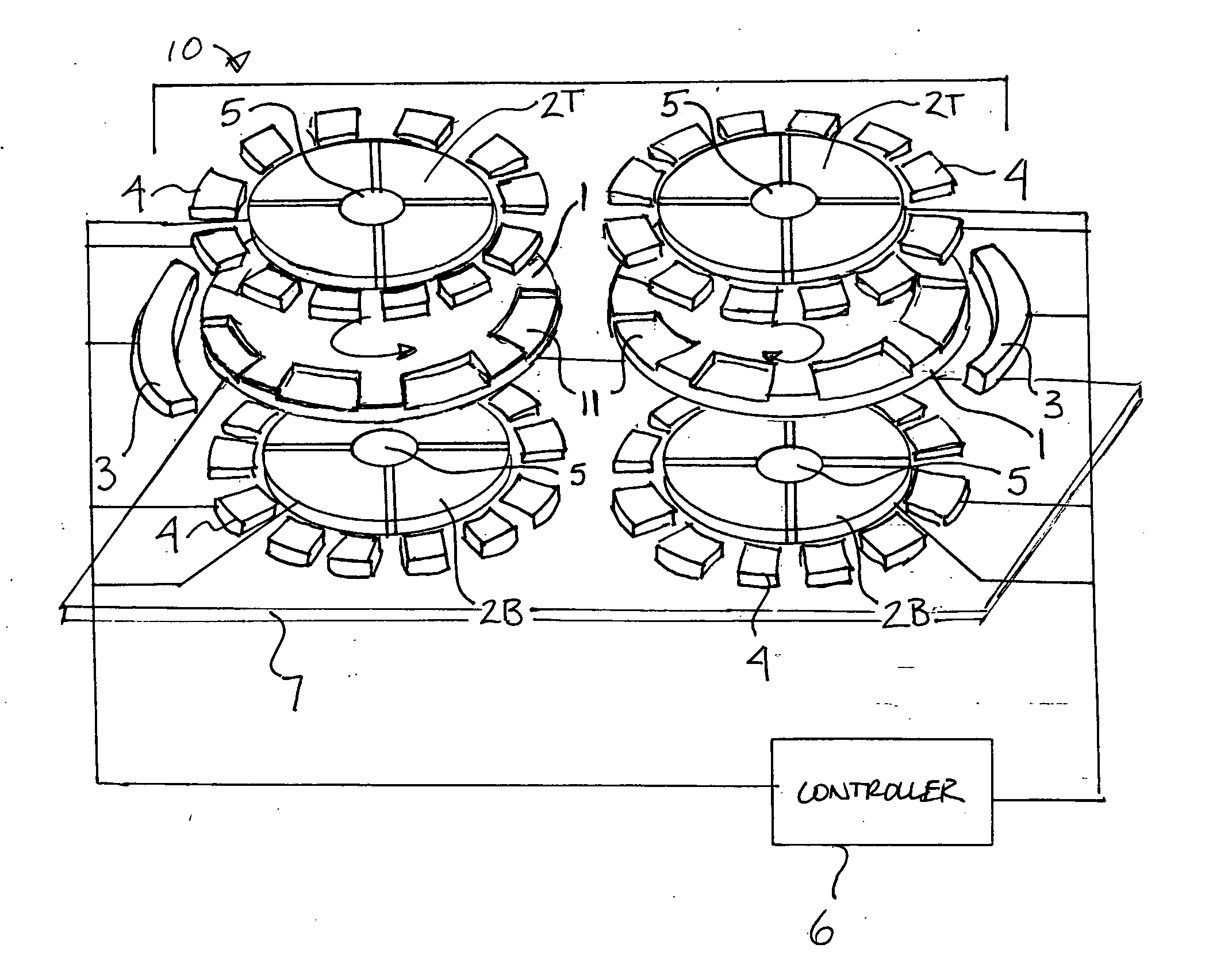
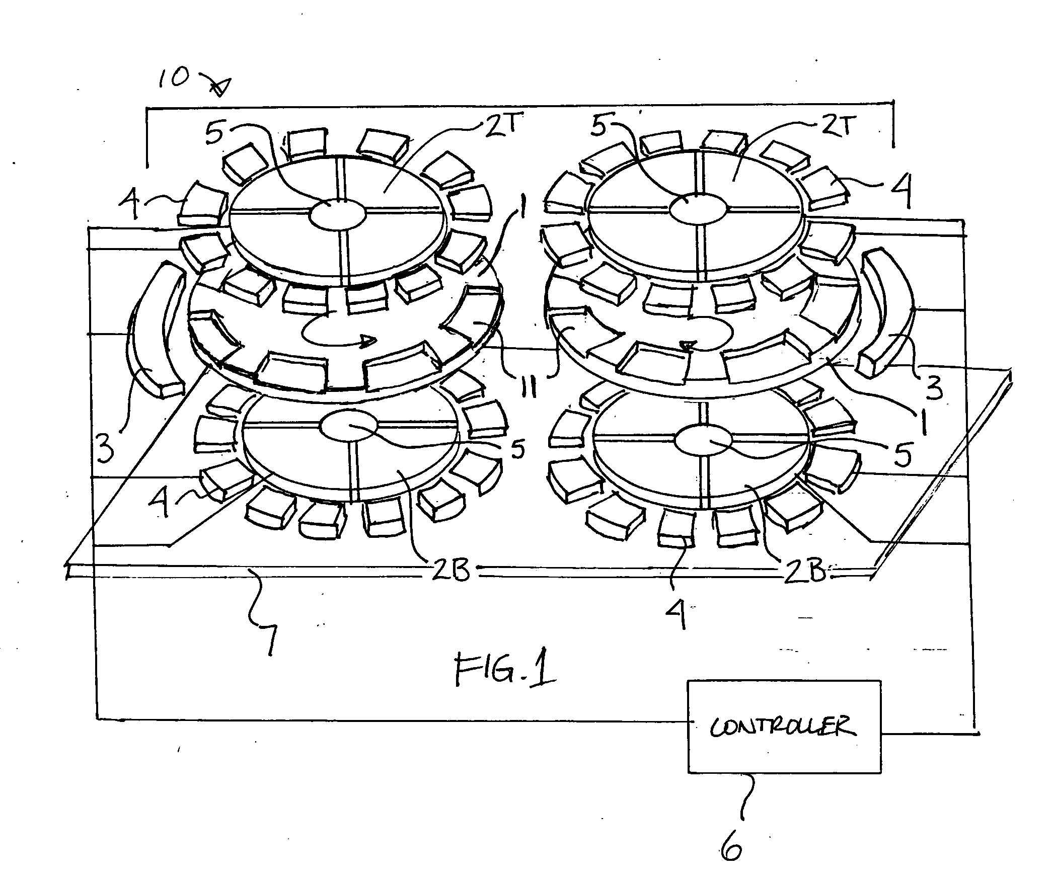
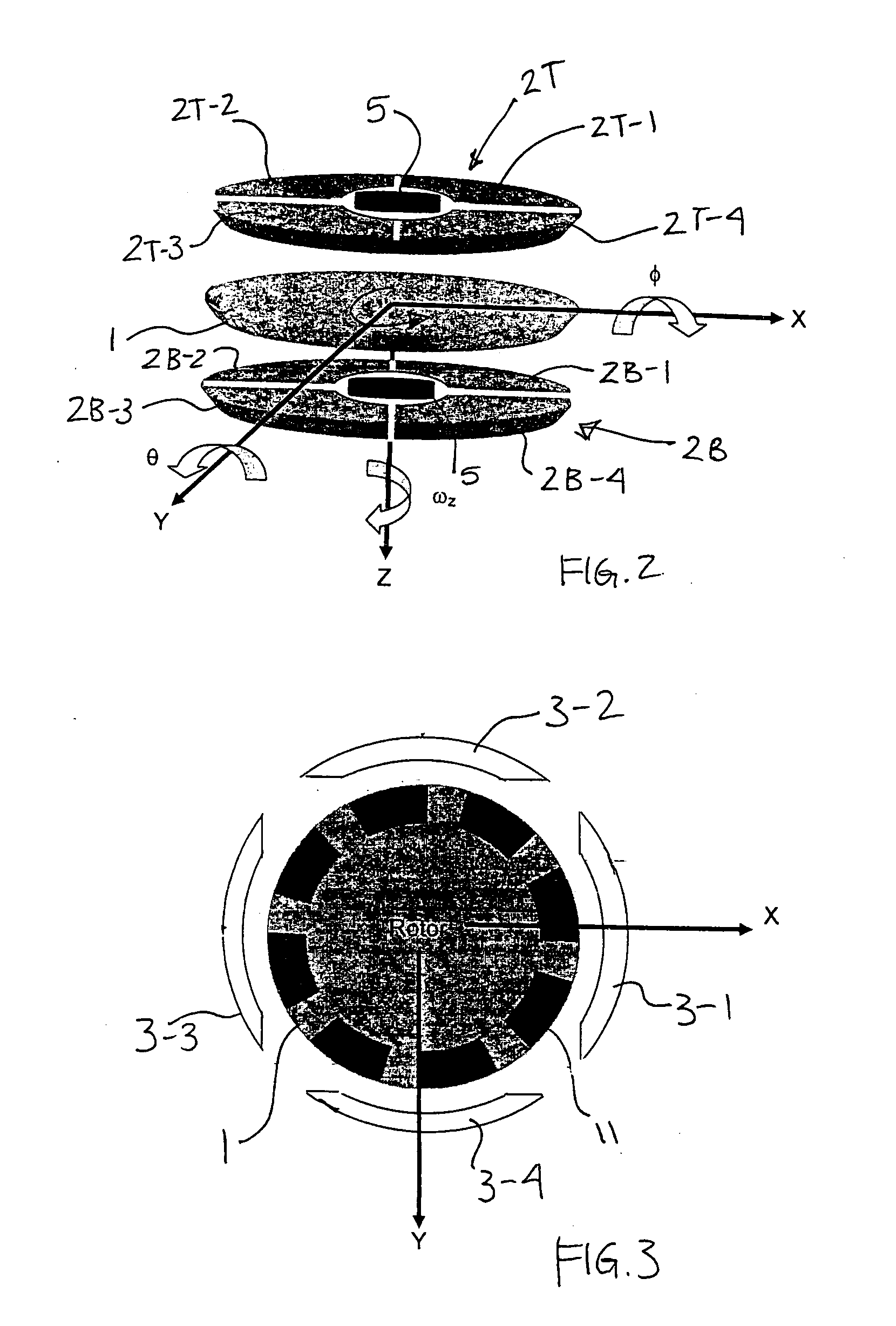
[0016]FIG. 1 shows an illustrative embodiment of a motion sensor 10 in accordance with aspects of the invention. One or more rotors 1 may be arranged to rotate about an axis relative to stators 2 and lateral electrodes 3 without contact with any physical support. In this illustrative embodiment, two rotors 1 are arranged to rotate in opposite directions (i.e., counter-rotate) about parallel axes oriented in the z-direction in a fr...


PUM


Abstract

A motion sensor may detect linear and / or angular acceleration and / or angular velocity of a body relative to one axis, two orthogonal axes or three orthogonal axes. Movement of the body or reference structure may be detected relative to one or more spinning rotors. The rotor(s) may be suspended for rotation and / or other movement relative to the reference structure without physical contacting the reference structure. In one embodiment, the rotor(s) may be electrostatically suspended in such a way that movement of the rotor(s) relative to the reference structure may be detected.

Description

[0001] Aspects of the invention were made with Government support under Contract Nos. N00178-02-C-1043, N00178-03-C-1059 awarded by the Missile Defense Agency (MDA) and awarded by the Navy. The Government may retain certain rights in this invention.BACKGROUND OF INVENTION [0002] This invention relates to detecting motion, and particularly to a gyroscopic-type device that can be used to detect acceleration and / or speed of motion of a body. [0003] Small, high accuracy, robust attitude solutions are highly sought after in many military and commercial applications. Military entities, in particular, are interested in an accurate, shock / vibration resistant sensor for use in missiles, projectiles, etc. that measure body accelerations and angular rotation rates. Commercial entities are interested in small, low cost, accurate attitude solutions for various purposes, such as in automobile and other vehicle sensing systems. Low cost sensor packages using Micro-Electro-Mechanical Systems (MEMS)...

Claims


Application Information

Patent Timeline
IPC IPC(8): G01P9/00
CPCG01C19/24G01P3/26G01P13/00G01P15/08G01P15/0888
Inventor GREENE, MICHAEL E.TRENT, VICTOR S.
Owner ARCHANGEL SYST
Learn More