Piston for automatic transmission

a technology of automatic transmission and piston, which is applied in the direction of mechanical actuators, mechanical apparatus, gearing, etc., can solve the problems of increasing the power loss of automatic transmission, deteriorating the durability etc., to improve the durability and operating efficiency of the piston and the frictional coupling elements, and improve the durability.

Active Publication Date: 2006-05-04
TOYOTA JIDOSHA KK
View PDF5 Cites 3 Cited by
  • Summary
  • Abstract
  • Description
  • Claims
  • Application Information

AI Technical Summary

Benefits of technology

[0007] The present invention was made in the light of the background art discussed above. It is therefore an object of the present invention to provide a piston for an automatic transmission, which includes a cylindrical wall portion provided by a first piston member and a bottom wall portion provided by a second piston member and which has improved durability and operating efficiency and assures improved durability of frictional coupling elements and improved power transmitting efficiency of the automatic transmission. This object may be achieved according to any one of first through twelfth aspects of the invention which are described below.
[0008] The first aspect of this invention provides a piston for an automatic transmission, including: (a) a cylindrical wall portion provided by a first piston member; (b) a bottom wall portion provided by a second piston member; and (c) an engaging portion at which the first and second piston members are engaged with each other such that the first piston member is movable relative to the second piston member in an axial direction of the piston by a small distance, wherein an improvement comprises the piston further including (d) an elastic structure which is provided at the engaging portion, and which biases the first piston member in the axial direction, so as to restrain movement of the first piston member relative to the second piston member in the axial direction.
[0020] In the piston constructed according to any one of the first through twelfth aspects of the invention, the first piston member is biased by the elastic structure in the axial direction, with a result of substantial elimination of a rattling movement of the first piston member in the axial direction. This arrangement is effective to prevent an unnecessary contact of the first piston member with a set of frictional coupling elements, making it possible to improve the durability and operating efficiency of the piston and the durability of the frictional coupling elements.
[0021] In the piston constructed according to any one of the second through fifth and ninth aspects of the invention, each of the at least one elastic lug, which is provided by the portion of the second piston member that is bent or inclined with respect to the radial direction, is held in contact with the radially extending surface of the corresponding one of the at least one engaging groove, whereby the first piston member is biased in the axial direction by the at least one elastic lug. In the piston constructed according to any one of the sixth, seventh and tenth aspects of the invention, each of the at least one elastic lug, which is provided by the portion of the first piston member that is bent or inclined with respect to the axial direction, is held in contact with the radially extending surface of the second piston member, whereby the first piston member is biased in the axial direction by the at least one elastic lug. In the piston constructed according to either one of the eighth and eleventh aspects of the invention, the first piston member is biased in the axial direction by the elastic member interposed between the first and second piston members. Therefore, each of each of the second through eleventh aspects of the invention, which corresponds to a preferred arrangement of the first aspect of the invention, provides substantially the same effect as the first aspect of the invention.
[0022] Each of the third and fourth aspects of the invention corresponds to a preferred arrangement of the second aspect of the invention, and accordingly provides substantially the same effect as the second aspect of the invention. Further, in the fourth aspect of the invention in which each of the at least one elastic lug is provided by a portion of the corresponding engaging protrusion, a biasing force generated by each elastic lug can be made smaller whereby the first and second piston members can be further easily assembled into the piston, as compared with an arrangement in which each elastic lug is provided by an entirety of the corresponding engaging protrusion.
[0023] In each of the fifth and seventh aspects of the invention, since each of the at least one elastic lug has the surface held in contact with the radially extending surface defining the corresponding engaging groove, namely, since each elastic lug is held in contact with the radially extending surface in a so-called “surface-to-surface” contact manner, each elastic lug is given an improved durability.

Problems solved by technology

Where the piston is constituted by the first piston member providing the cylindrical wall portion and the second piston member providing the bottom wall portion, which are fixed to each other with a snap ring or the like, a small gap inevitably exists in the axial direction of the piston, between the first and second piston members fixed together with the snap ring, due to axial dimensional errors within a predetermined tolerance, so that the first and second piston members are undesirably movable relative to each other in the axial direction of the piston, in the presence of the above-indicated gap.
Accordingly, the first piston member tends to have a rattling movement in the axial direction, giving rise to a risk of unnecessary abutting contact of the first piston member with the outermost one of the frictional coupling elements, which may cause unnecessary mutual frictional contact of the frictional coupling elements, leading to so-called “dragging” of the clutch or brake, and consequent deterioration of durability of the piston and the frictional coupling elements, and an increase in power loss of the automatic transmission due to the dragging.

Method used


Image

  • Piston for automatic transmission
  • Piston for automatic transmission
  • Piston for automatic transmission

Examples


Embodiment Construction

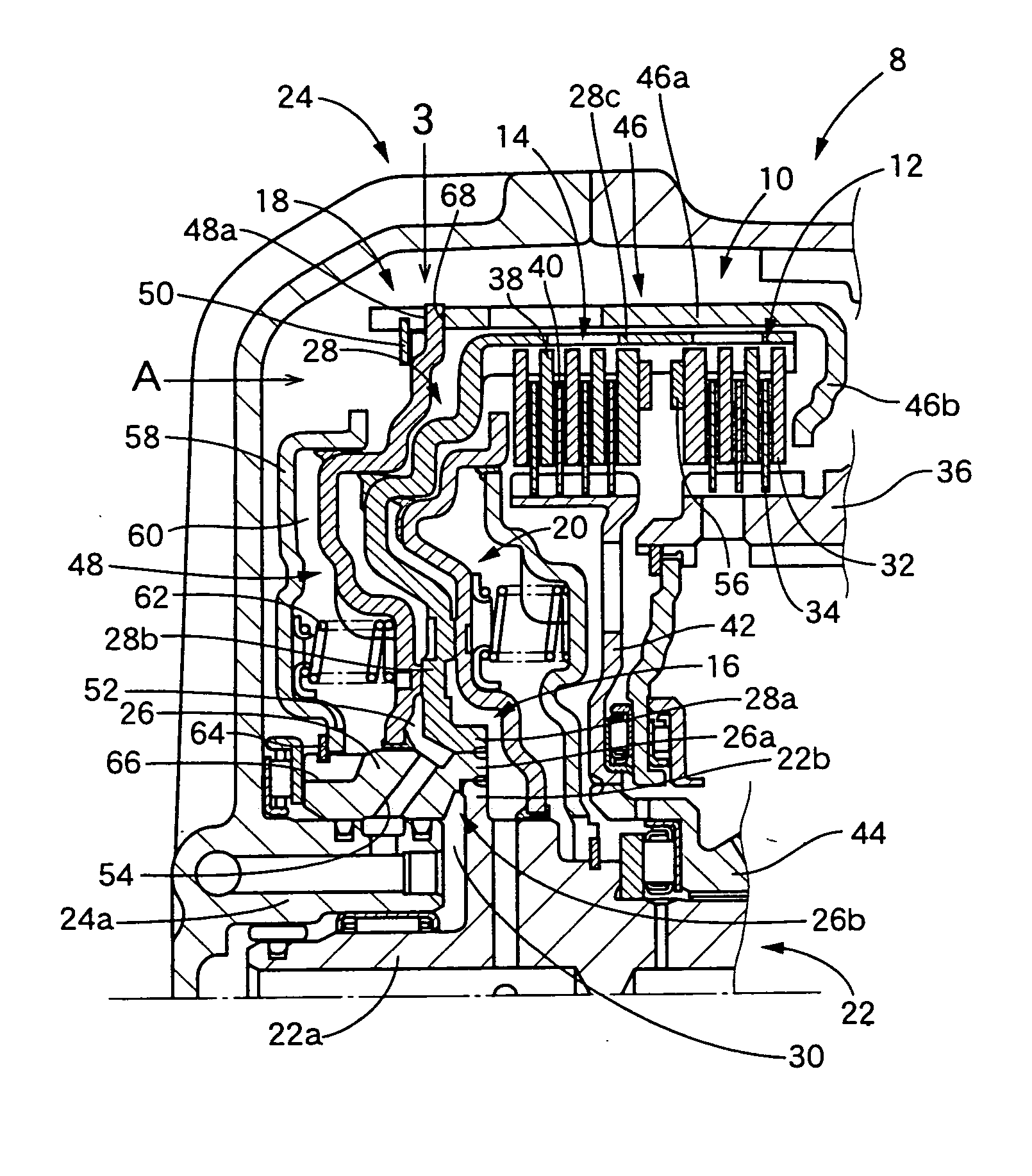
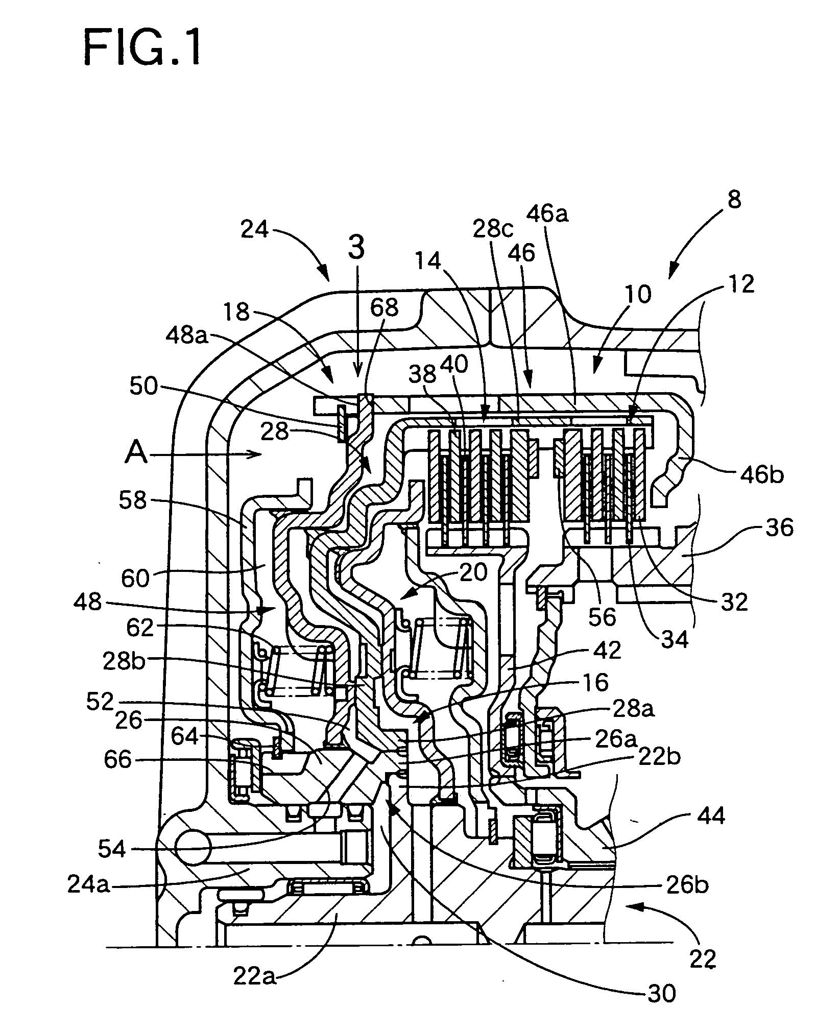
[0039] Referring first to the side elevational view in cross section of FIG. 1, there is shown a part of an automatic transmission 8 which is provided with a clutch device 10 including a piston in the form of a radially outer piston 18 constructed according to a first embodiment of this invention.

[0040] The clutch device 10 is of a double clutch construction, and includes: a clutch drum 16 supporting a first set of frictional coupling elements 12 and a second set of frictional coupling elements 14; the above-indicated radially outer piston 18 disposed radially outwardly of the clutch drum 16 so as to cover the clutch drum 16; and a radially inner piston 20 disposed radially inwardly of the clutch drum 16.

[0041] The automatic transmission 8 has a casing 24, and an input shaft 22 which is rotatably supported at its end portion 22a by the casing 24. The input shaft 22 has a flange portion 22b which is located at an axial position near the end portion 22a. The flange portion 22b exten...


PUM


Abstract

A piston for an automatic transmission includes: (a) a cylindrical wall portion provided by a first piston member; (b) a bottom wall portion provided by a second piston member; and (c) an engaging portion at which the first and second piston members are engaged with each other such that the first piston member is movable relative to the second piston member in an axial direction of the piston by a small distance. The piston is characterized by further including (d) an elastic structure which is provided at the engaging portion, and which biases the first piston member in the axial direction, so as to restrain movement of the first piston member relative to the second piston member in the axial direction.

Description

[0001] This application is based on Japanese Patent Application No. 2004-321132 filed on Nov. 4, 2004, the content of which is incorporated hereinto by reference. BACKGROUND OF THE INVENTION [0002] 1. Field of the Invention [0003] The present invention relates in general to a piston operable to force frictional coupling elements of a clutch or brake provided in an automatic transmission, against each other to place the clutch or brake in its engaged state. [0004] 2. Discussion of Related Art [0005] A known automatic transmission includes clutches and brakes each of which is provided with frictional coupling elements in the form of a plurality of friction plates, so that the automatic transmission is automatically shifted by selectively engaging and releasing the clutches and brakes. The frictional coupling elements are forced against each other by a piston, to place each clutch or brake in its engaged state. JP-H09-32919A discloses an example of such a piston, which consists of two ...

Claims


Application Information

Patent Timeline
Patent Type & Authority Applications(United States)
IPC IPC(8): F16J1/00F16D13/70F16D25/0638F16D25/12
CPCF16D25/0638F16D25/10F16D2048/0212F16H63/3026F16D13/70F16D25/06F16H3/44
Inventor ONISHI, HIROFUMIYASUDA, YUJI
Owner TOYOTA JIDOSHA KK
Why Eureka
Try Eureka