Tool display rack having holding and rotation test functions

Inactive Publication Date: 2006-05-04
LIYIDE
View PDF8 Cites 18 Cited by
  • Summary
  • Abstract
  • Description
  • Claims
  • Application Information

AI Technical Summary

Benefits of technology

[0008] Another objective of the present invention is to provide a tool display rack, wherein the main body of the tool display rack is integrally formed with the mounting portion, the elastic portions and the holding portions, so that the tool display rack has a simplified construction, thereby decreasing costs of fabrication.
[0009] A furth

Problems solved by technology

However, the tool display rack needs to provide a locking member 50, so that the tool

Method used


Image

  • Tool display rack having holding and rotation test functions
  • Tool display rack having holding and rotation test functions
  • Tool display rack having holding and rotation test functions

Examples


Example

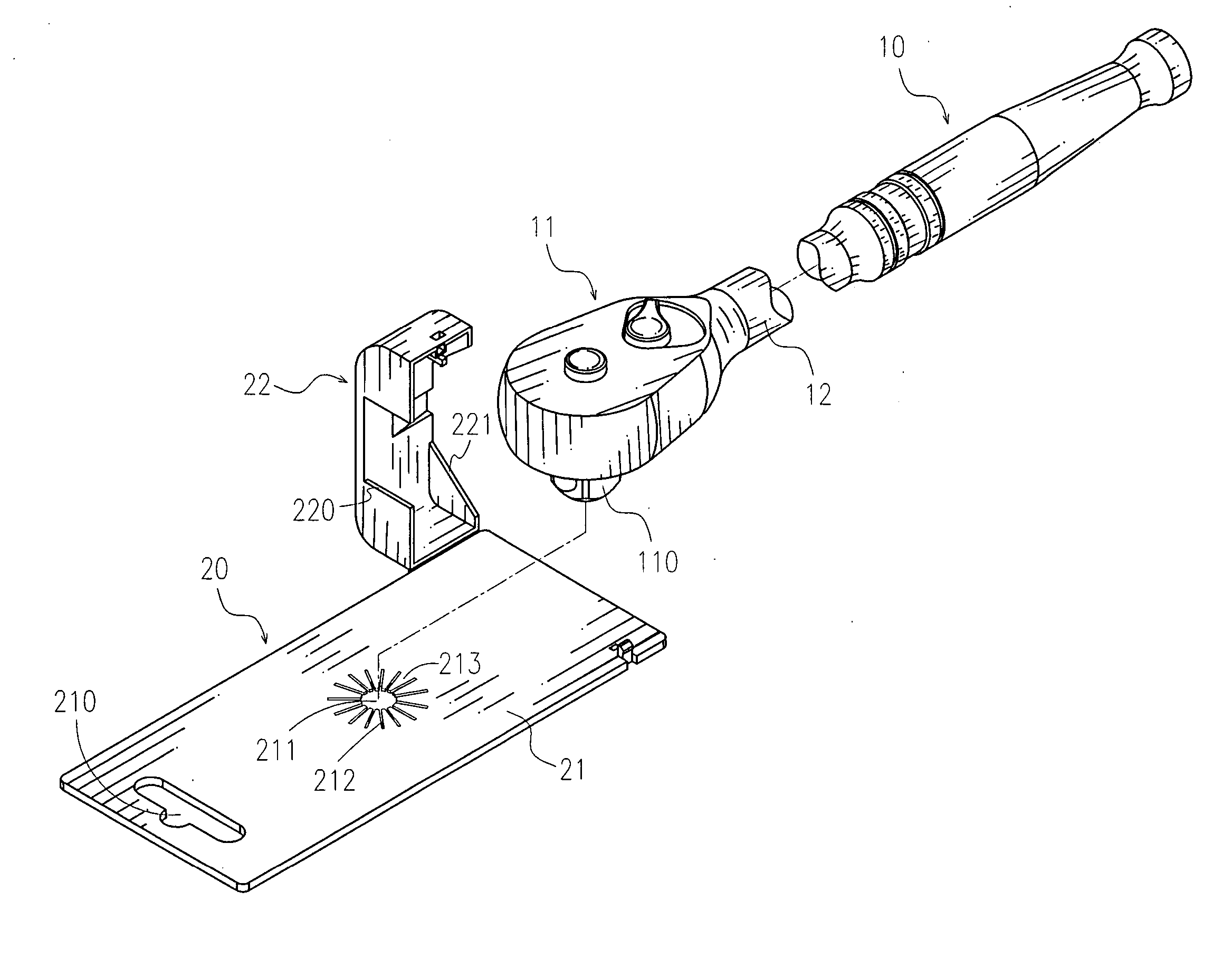
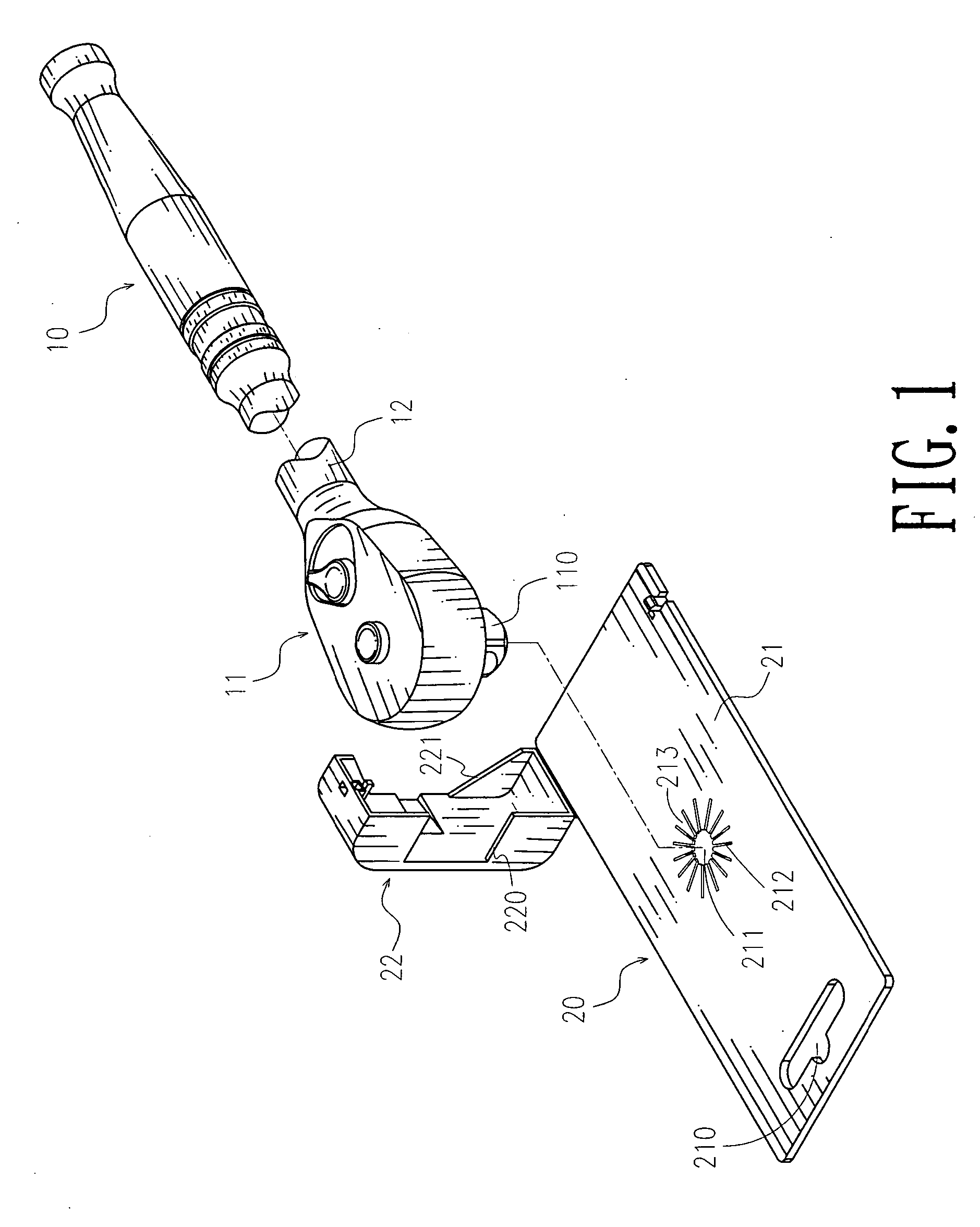
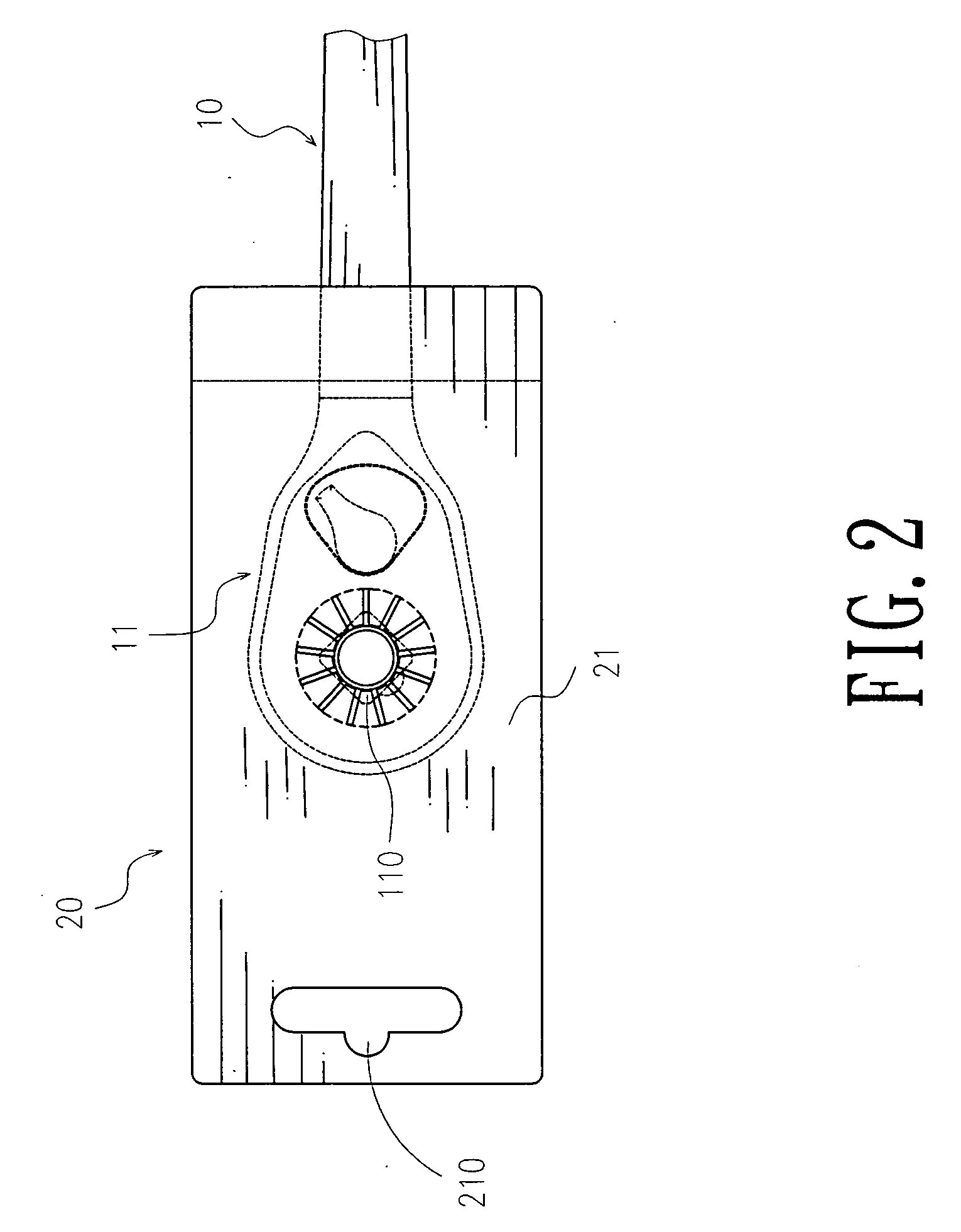
[0026] Referring to the drawings and initially to FIGS. 1-4, a tool display rack 20 in accordance with a first embodiment of the present invention is used for mounting a tool 10. The tool 10 has a drive head 11 and a neck portion 12. The drive head 11 of the tool 10 has a square drive stud 110.

[0027] The tool display rack comprises a main body 21, a mounting portion 211 mounted on the main body 21 to allow passage of the drive stud 110 of the tool 10 and having an inner edge closely urged on a peripheral wall of the drive stud 110 of the tool 10 to produce a contact friction therebetween, and a pressing member 22 pivotally mounted on the main body 21 and urged on the neck portion 12 of the tool 10.

[0028] The main body 21 has a first end formed with a hanging portion 210 for hanging the main body 21. The mounting portion 211 is mounted on a mediate portion of the main body 21 and is preferably a through hole having a diameter slightly smaller than a size of the drive stud 110 of th...


PUM


Abstract

A tool display rack includes a main body, a mounting portion mounted on the main body to allow passage of the drive stud of a tool and having an inner edge closely urged on a peripheral wall of the drive stud of the tool to produce a contact friction therebetween, and a pressing member pivotally mounted on the main body and urged on the neck portion of the tool. Thus, the holding portions of the mounting portion are deformed and urged on the peripheral wall of the drive stud of the tool closely so as to clamp the drive stud of the tool, so that the drive stud of the tool is secured in the mounting portion rigidly and stably.

Description

BACKGROUND OF THE INVENTION [0001] 1. Field of the Invention [0002] The present invention relates to a tool display rack, and more particularly to a tool display rack having holding and rotation test functions. [0003] 2. Description of the Related Art [0004] A conventional tool display rack in accordance with the prior art shown in FIGS. 6 and 7 comprises a main body 40 formed with a circular hole 41 for mounting the square drive stud 310 of the drive head 31 of a wrench 30, and a pressing member 42 secured on the main body 40 and urged on the neck portion of the wrench 30. However, the wrench 30 cannot be rotated relative to the main body 40 of the tool display rack to test the rotation angle of the drive stud 310 of the wrench 30. [0005] Another conventional tool display rack in accordance with the prior art shown in FIGS. 8 and 9 comprises a main body 40 formed with a square hole 43 for mounting the square drive stud 310 of the drive head 31 of the wrench 30. Thus, the square dri...

Claims


Application Information

Patent Timeline
IPC IPC(8): A47F7/00
CPCB65D73/0014B65D73/0064
Inventor TUAN MU, HSIEN-CHUNG
Owner LIYIDE
Why Eureka
Try Eureka