Photomultiplier and radiation detector
a radiation detector and multi-layer technology, applied in the manufacture of electrode systems, electric discharge tubes/lamps, instruments, etc., can solve the problems of sealing container appearance defects and functional defects, and achieve the effect of facilitating the positioning of the base member and lowering the manufacturing cos
- Summary
- Abstract
- Description
- Claims
- Application Information
AI Technical Summary
Benefits of technology
Problems solved by technology
Method used
Image
Examples
first embodiment
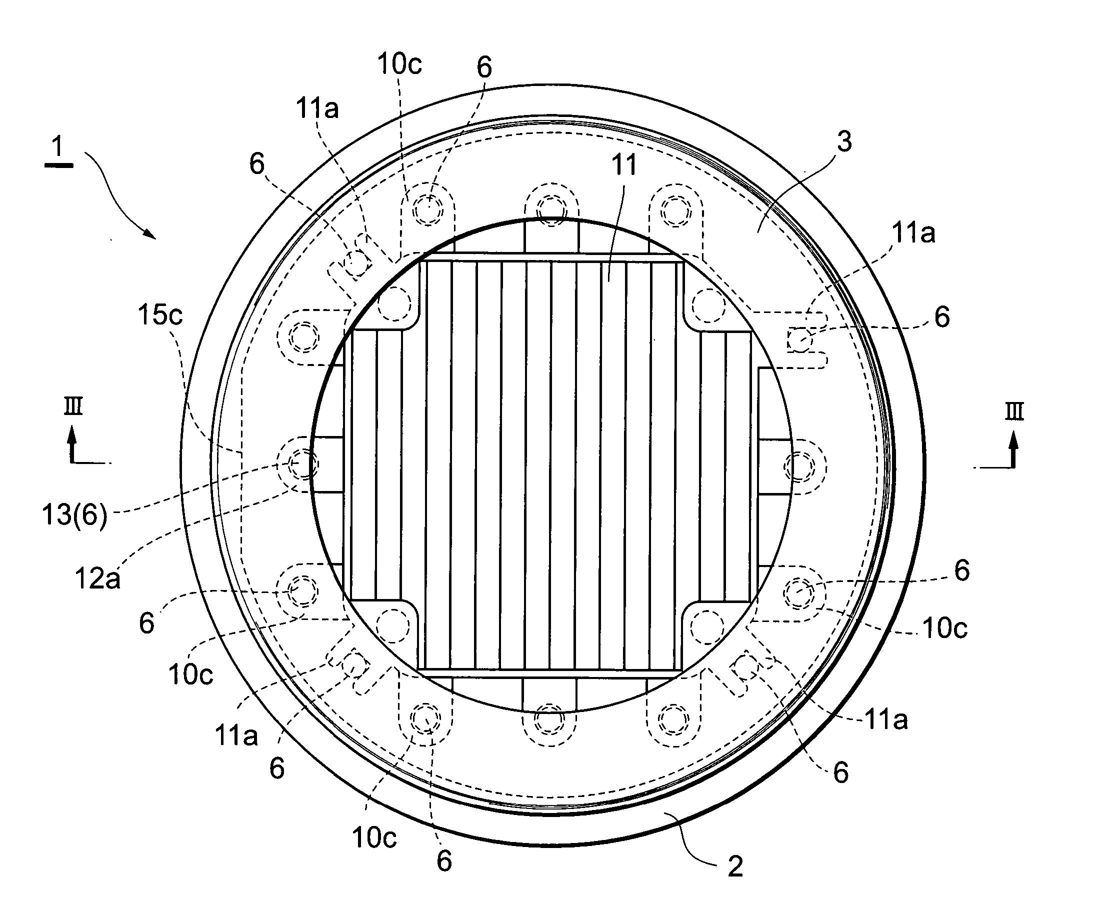
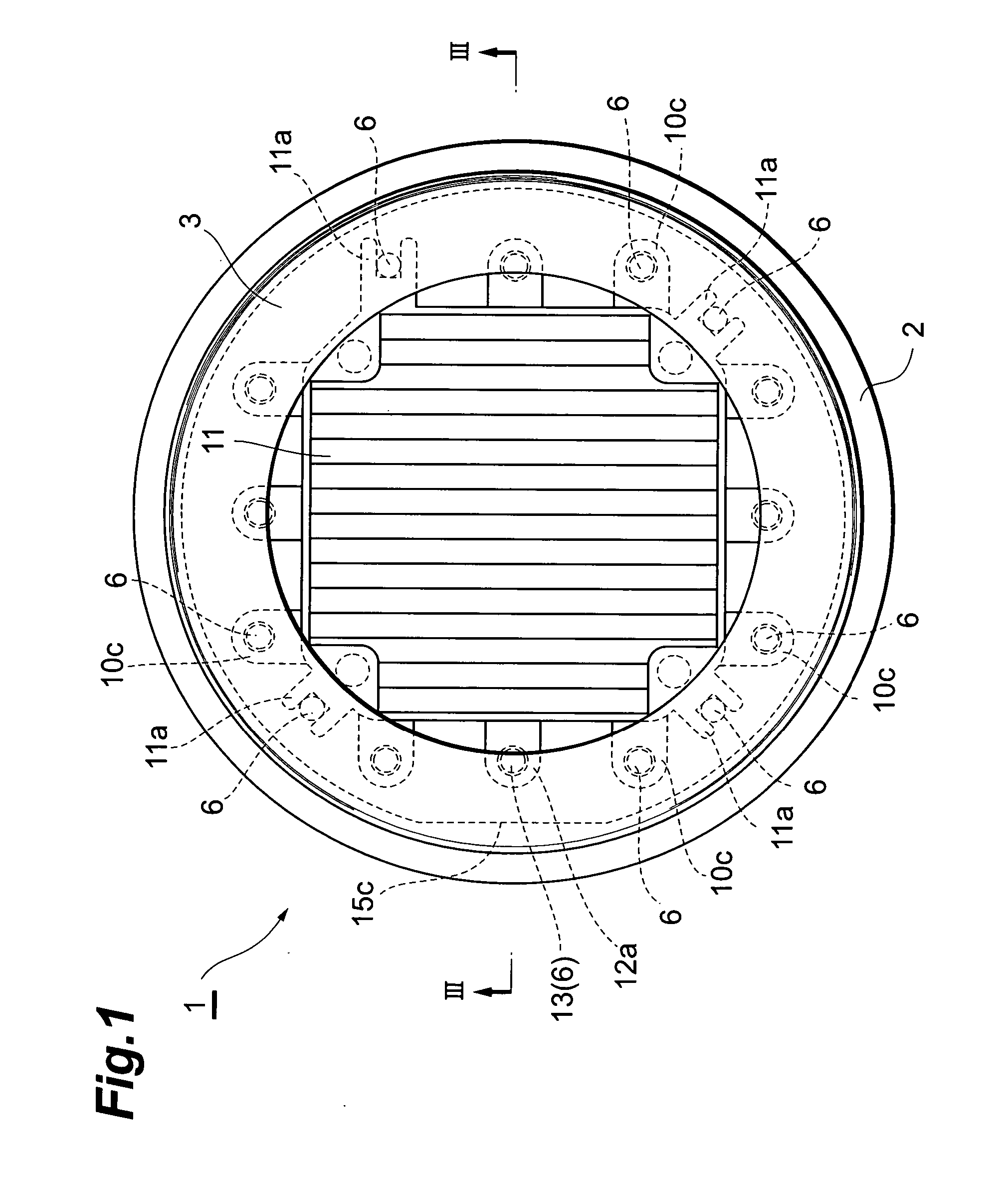
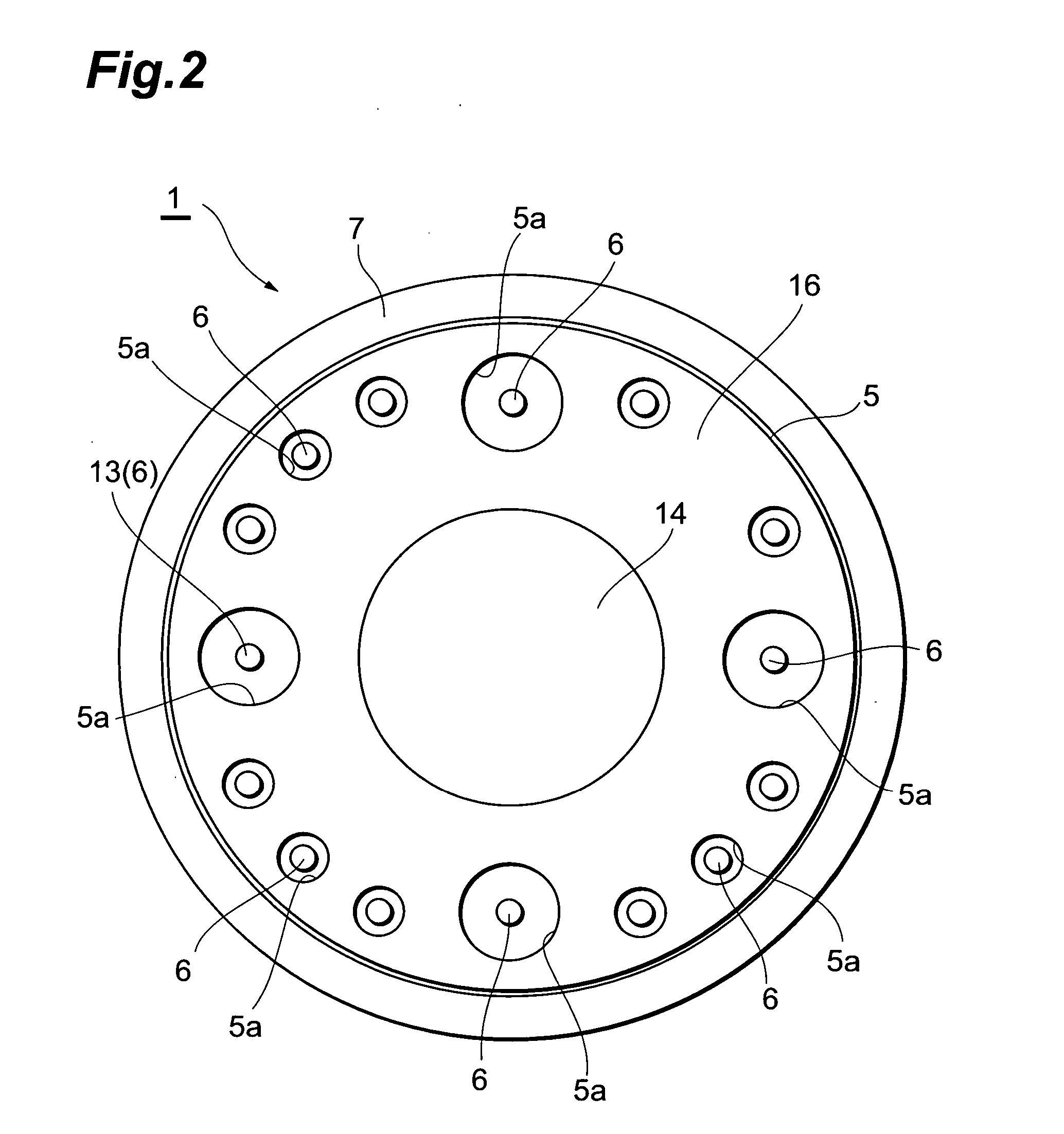
[0049]FIG. 1 and FIG. 2 are a plan view and a bottom view, respectively, of a first embodiment of a photomultiplier by this invention, and FIG. 3 is a sectional view taken along line III-III in FIG. 1. In FIG. 1 to FIG. 3, a photomultiplier 1 is arranged as a device that emits electrons upon incidence of light from the exterior and multiplies and outputs the electrons as a signal.
[0050] As shown in FIG. 1 to FIG. 3, the photomultiplier 1 has a metal side tube 2 with a substantially cylindrical shape. As shown in FIG. 3, a glass light receiving plate 3 is fixed in an airtight manner to an open end at the upper side (one side) of the side tube 2, and a photoelectric surface 4, for converting the light made incident through the light receiving plate 3 into electrons, is formed on the inner surface of the light receiving plate 3. Also, a disk-like stem 5 is positioned at an open end at the lower side (other side) of the side tube 2 as shown in FIG. 2 and FIG. 3. A plurality (15) of con...
second embodiment
[0078] As shown in FIG. 17, a photomultiplier 28 of a second embodiment has a stem 29 arranged as a two-layer structure of a disk-like base member 30, of the same quality as the base member 14, and the upper holding member 15, joined to the upper side (inner side) of the base member 30, and thus differs from the photomultiplier 1 of the first embodiment, wherein the stem 5 is arranged as a three-layer structure of the base member 14, the upper holding member 15, and the lower holding member 16.
[0079] That is, the stem 29 of the photomultiplier 28 is not provided with the lower holding member 16, and the base member 30 has, along outer peripheral portions of the base member 30, a plurality (15) of openings 30a, with each of which the diameter of the upper half is made substantially equal to the outer diameter of each stem pin 6 as shown in FIG. 18 and the diameter of the lower half is made larger than the outer diameter of each stem pin 6 as shown in FIG. 19. Of the openings 30a of ...
third embodiment
[0105] As shown in FIG. 27, a photomultiplier 34 of a third embodiment has a stem 35 arranged as a single-layer structure of a disk-like base member 36, of the same quality as the base member 14, and thus differs from photomultiplier 1 of the first embodiment, wherein the stem 5 is arranged as a three-layer structure of the base member 14, the upper holding member 15, and the lower holding member 16.
[0106] That is, the stem 35 of the photomultiplier 34 is not provided with the upper holding member 15 and the lower holding member 16, and the base member 36 has, along outer peripheral portions of base member 36, a plurality (15) of openings 36a, with each of which the diameter of an intermediate portion is made substantially equal to the outer diameter of each stem pin 6 and the diameters of upper and lower portions are made larger than the outer diameter of each stem pin 6 as shown in FIG. 27 to FIG. 29. Of the openings 36a of the base member 36, the upper and lower portions of thre...
PUM
 Abstract
Description
Claims
Application Information
 - R&D
- Intellectual Property
- Life Sciences
- Materials
- Tech Scout
- Unparalleled Data Quality
- Higher Quality Content
- 60% Fewer Hallucinations
Browse by: Latest US Patents, China's latest patents, Technical Efficacy Thesaurus, Application Domain, Technology Topic, Popular Technical Reports.
© 2025 PatSnap. All rights reserved.Legal|Privacy policy|Modern Slavery Act Transparency Statement|Sitemap|About US| Contact US: help@patsnap.com


