Sensor arrangement and method for regulating the distance of motor vehicles

a technology of motor vehicles and sensors, applied in the field of sensor systems, can solve problems such as front of the center of the vehicle, and achieve the effects of reducing blind spots on both sides, increasing the reliability of the sensor system, and facilitating recognition

Inactive Publication Date: 2006-05-04
ROBERT BOSCH GMBH
View PDF19 Cites 30 Cited by
  • Summary
  • Abstract
  • Description
  • Claims
  • Application Information

AI Technical Summary

Benefits of technology

[0005] In contrast, the sensor system of the present invention offers the advantage that it is possible to achieve a considerable reduction in the blind spots on both sides of the vehicle using conventional sensors that are already tried and proven, and with comparatively insignificant modifications of the evaluation algorithms. Further advantages are that the redundancy and therefore the reliability of the sensor system is increased, and certain malfunctions, for example, due to sensor misalignment or due to temporary blinding of a sensor caused by snowfall, can be recognized substantially more easily and reliably during continuous operation.
[0006] In the sensor system according to the present invention, two conventional long-range sensors are positioned in such a way on both sides of the longitudinal center axis of the vehicle that their locating angular ranges together cover the entire vehicle width as of a first distance d1, and overlap one another as of a second distance d2. This arrangement makes it possible to substantially shorten the blind spots to the right and left of the locating ranges, so that, for example, a stop and go control can be implemented without an additional short-range sensor system, although the locating angular range of each individual sensor is, for example, only ±7°. However, in the case of a particularly cost-effective design approach using just precisely two sensors, an additional blind spot then results in front of the center of the vehicle. This blind spot is relatively small, however, and the case, which is thus anyway very unlikely, that a narrow preceding vehicle, e.g. a two-wheeler, will disappear in this blind spot can be taken into account by a simple adaptation of the method for distance control. In this context, use is made in particular of the circumstance that an object cannot get into this blind spot without it having been detected by at least one of the sensors beforehand.
[0010] In the normal distance range, e.g. at distances of 10 m or more, objects in one's own traffic lane are detected using the arrangement of two sensors according to the present invention. This yields the possibility of checking the distance and angle data, measured by the sensors, for their consistency by triangulation, so that, for example, errors in the angular adjustment of one or both sensors may be easily recognized and, optionally, automatically corrected in the signal evaluation. In the same way, a failure or blinding of one of the sensors is immediately recognizable.

Problems solved by technology

However, in the case of a particularly cost-effective design approach using just precisely two sensors, an additional blind spot then results in front of the center of the vehicle.

Method used


Image

  • Sensor arrangement and method for regulating the distance of motor vehicles
  • Sensor arrangement and method for regulating the distance of motor vehicles
  • Sensor arrangement and method for regulating the distance of motor vehicles

Examples


Embodiment Construction

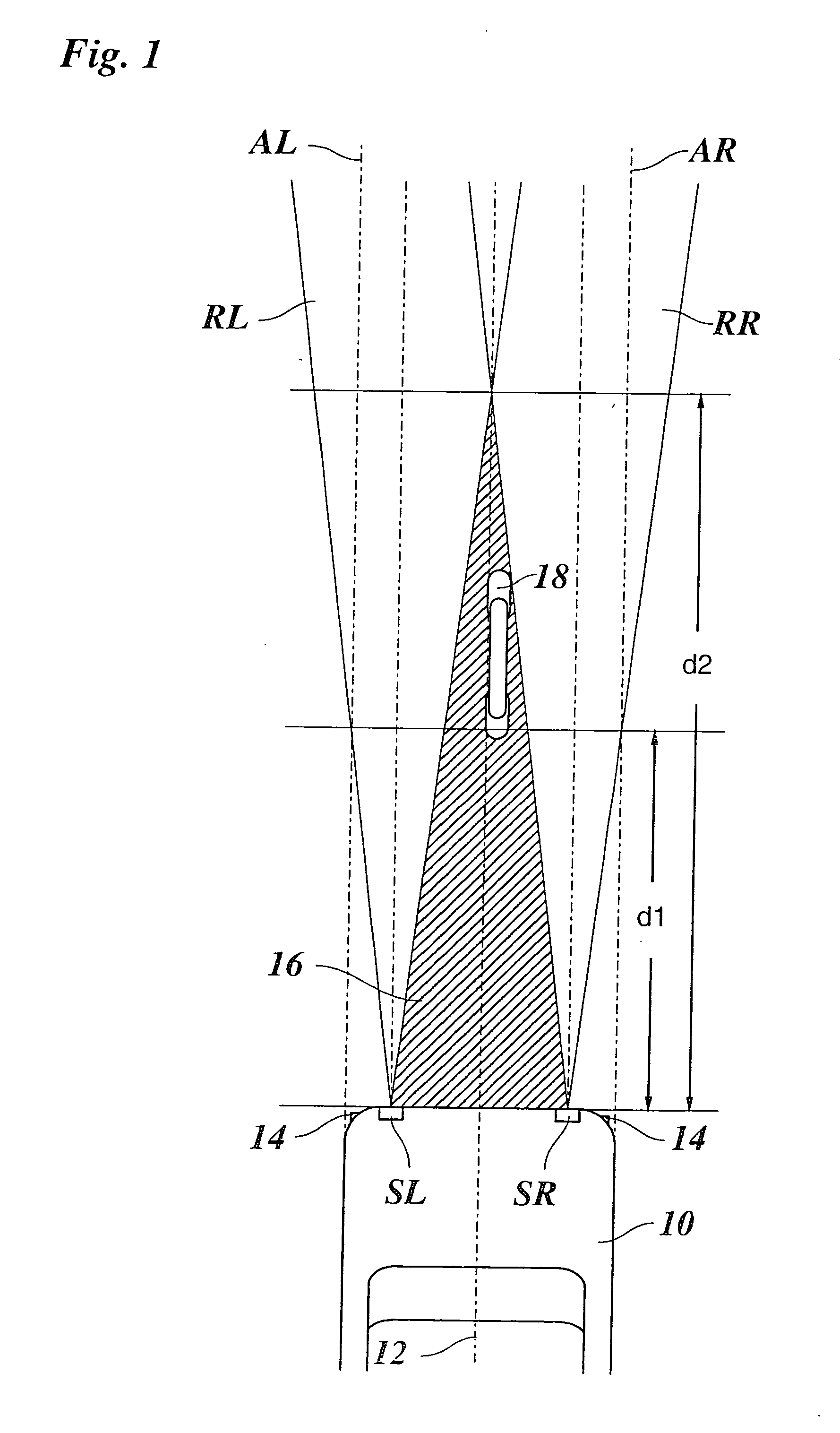
[0015] In FIG. 1 at the lower edge, the front end of a vehicle 10 is shown in which, in the region of the front bumper, a sensor system is provided made up of two sensors SR and SL arranged symmetrically with respect to longitudinal center axis 12 of the vehicle. For example, these sensors are angular-resolution FMCW radar sensors which are able to detect the distances and relative speeds of objects in a distance range between 3 m and approximately 200 m. The extreme short range below 3 m is covered by additional parking-assistance sensors 14. Each of the two sensors SR and SL has a locating angular range RR and RL, respectively, of ±7°. Optical axes AR and AL of the two sensors run parallel to longitudinal center axis 12 of the vehicle. The lateral displacement of sensors SR and SL with respect to longitudinal center axis 12 of vehicle 10 is approximately 60 cm. Given a typical vehicle width of 2 m, this means that the two locating angular ranges RR and RL together already cover th...


PUM


Abstract

A sensor system on motor vehicles for locating objects in front of the vehicle, wherein at least two sensors, each having a locating depth of at least 50 m, are arranged in such a way on both sides of longitudinal center axis of the vehicle that their locating angular ranges together cover the entire vehicle width as of a first distance d1, and overlap each other as of a second distance d2.

Description

FIELD OF THE INVENTION [0001] The present invention relates to a sensor system on motor vehicles which is used for locating objects in front of the vehicle, as well as a method for distance control with the aid of such a sensor system. BACKGROUND INFORMATION [0002] Motor vehicles are frequently equipped with a so-called ACC system that permits distance control, i.e. an adaptive cruise control. This system includes a distance sensor, e.g. a radar sensor or, alternatively, also a lidar sensor, with which it is possible to measure the distances to objects located in front of the vehicle. In the case of a radar sensor, it is also possible to directly measure the relative speeds. When the sensor detects a target object, e.g. a preceding vehicle, the speed of one's own vehicle is automatically adjusted so that the preceding vehicle is followed at an appropriate safety distance. When no relevant target object is detected, the speed is regulated to a desired speed selected by the driver. [0...

Claims


Application Information

Patent Timeline
Patent Type & Authority Applications(United States)
IPC IPC(8): G01S13/93B60Q1/00G08G1/16B60R21/00G01S13/931G01S7/03
CPCG01S13/931G01S2013/9321G01S2013/9325G01S2013/9375G01S2013/9389G01S2013/9346G01S2013/93275G01S2013/93185G01S2013/93271
Inventor BOECKER, JUERGENBRAEUCHLE, GOETZ
Owner ROBERT BOSCH GMBH
Why Eureka
Try Eureka