Communication method

a communication method and radio communication technology, applied in the field of radio communication system, can solve the problems of time-consuming, and concentrated load on the base station, and achieve the effect of preventing deterioration of system performan

Inactive Publication Date: 2006-05-04
HITACHI LTD
View PDF5 Cites 53 Cited by
  • Summary
  • Abstract
  • Description
  • Claims
  • Application Information

AI Technical Summary

Benefits of technology

[0014] By providing the emergency period in the slot, even when the sleep time intervals of the sensor node are changed, reassignment of slots to the sensor node is not required, thereby preventing deterioration of the performance of the system.
[0015] Furthermore, in the radio communication system of the present invention, when the sleep time intervals of the sensor node are changed, in order to notify the b...

Problems solved by technology

Therefore, when the TDMA method is used in an application in which the sleep time intervals of each of sensor nodes are intensely changed, the system performance is significantly deteriorated.
Secondly, when a plurality of sensor nodes simultaneously accesses the base station at initial access of the TDMA method, load is concentrated on the base station, and sometimes it takes time until the system is stabilized.
In the hazard ...

Method used


Image

  • Communication method
  • Communication method
  • Communication method

Examples


first embodiment

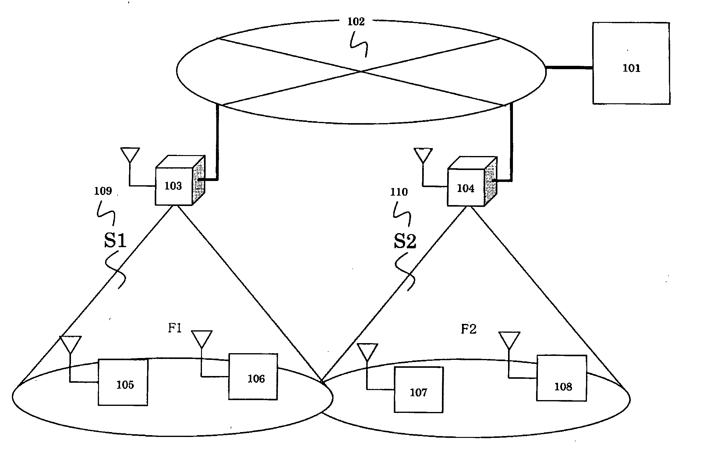
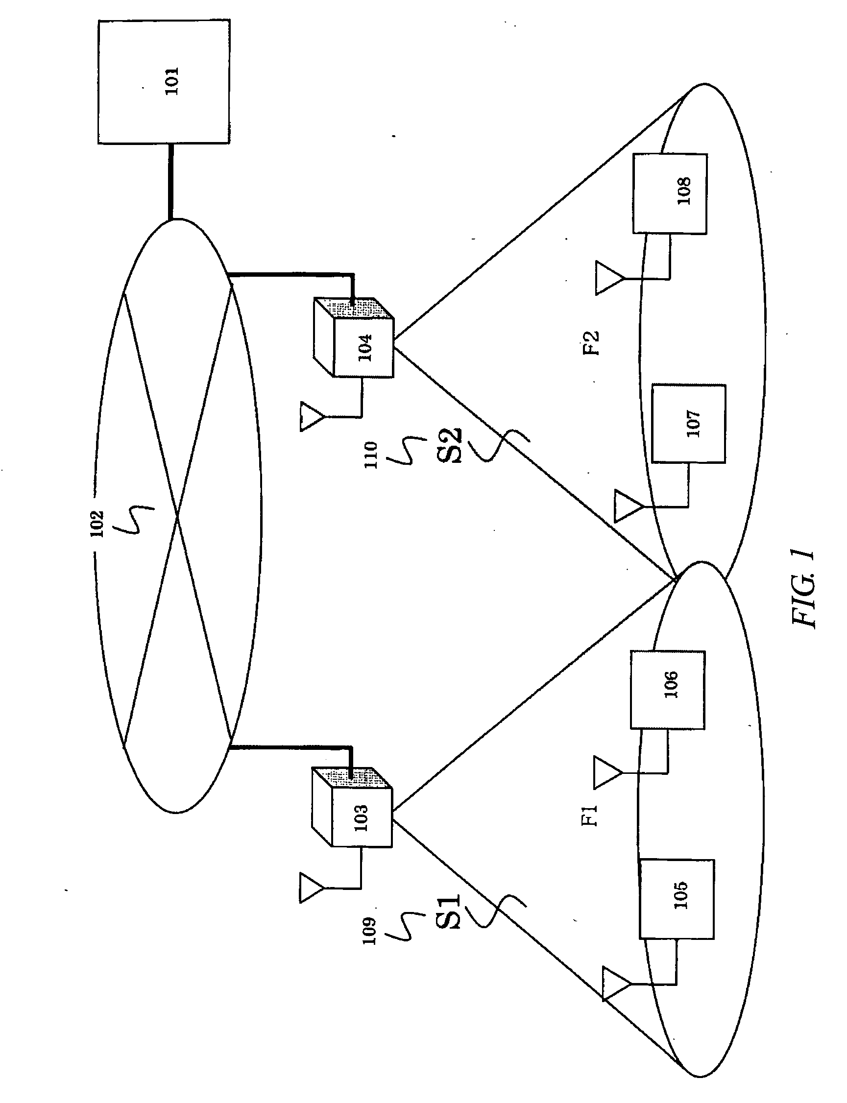
[0034] A first embodiment of a radio communication system according to the present invention will be described. In FIG. 1, a schematic diagram of the communication system of the present embodiment is shown. The present system comprises a management server (101) for performing overall control of the entire system, Internet (102), base stations (103 and 104), and sensor nodes (105, 106, 107, and 108). F1 and F2 described in the diagram denote frequencies used in data channels of the base stations, and S1 and S2 (109 and 110) denote service areas in which the base stations can manage the sensor nodes.

[0035] At predetermined intervals, each of the sensor nodes separately uses two operations, i.e., that in a sleep state in which, in hardware, power of the members except that of a timer circuit (e.g., RTC) is caused to be in an OFF-state, and that in an active state in which power of all circuits thereof is caused to be in an ON-state. In the active state of the sensor node, sensing is p...

second embodiment

[0068] A second embodiment of the present invention will be described. In the first embodiment, there has been described a situation in which the base station assigns the sensor nodes to the normal periods of the slots in the order that the IDs of the sensor nodes are registered in the base station. However, in the second embodiment, there described a situation in which, regardless of the order of registration, the base station randomly assigns the sensor nodes to the normal periods of the slots.

[0069] In FIG. 14, there shown a method of a case in which the sensor nodes are randomly assigned to the normal periods. Each of the sensor nodes performs initial access so as to perform registration with respect to the database of the base station. Then, each sensor node is subjected to time compensation with respect to other sensor nodes by use of the command Ack packet. The sensor nodes which have undergone time compensation are randomly assigned to the normal periods, and transmit packe...


PUM


Abstract

A radio communication system suitable for a sensor net system is provided. In a TDMA method, one slot is divided into four periods. Even when a majority of sensor nodes simultaneously perform access, they can settle in a steady state in high speed corresponding to the transition response of the system. Even when sleep time intervals of the sensor nodes are changed according to the priority thereof and the transmission intervals of the sensor nodes are not constant, the TDMA method control can be performed. Moreover, even when the transmission intervals of the sensor nodes are not constant, the original system performance is not deteriorated.

Description

CROSS-REFERENCE TO RELATED APPLICATION [0001] The present application claims priority from Japanese Patent Application JP 2004-315007 filed on Oct. 29, 2004, the content of which is hereby incorporated by reference into this application. TECHNICAL FIELD OF THE INVENTION [0002] The present invention relates to a radio communication system such as a sensor net for controlling and processing large volume information traffic. BACKGROUND OF THE INVENTION [0003] At present, radio congestion controlling methods in communication systems include mainly three methods, i.e., TDMA, FDMA, and CDMA. [0004] In the TDMA method, slots for dividing one frequency at predetermined time intervals are provided. Each of a plurality of sensor nodes can transmit packets through the slots of its own assigned from a base station, and each sensor node can use the entire band width during the assigned time period. The TDMA method requires highly accurate time synchronization, and the sensor nodes receive period...

Claims


Application Information

Patent Timeline
IPC IPC(8): H04B7/212H04Q7/24H04W72/12H04W74/04H04W84/18
CPCH04L1/1867H04W52/0235H04W72/10H04W74/0808H04W76/046H04W76/27Y02D30/70H04W72/56
Inventor SHIMOKAWA, ISAOYAMASHITA, SHUNZO
Owner HITACHI LTD
Why Eureka
Try Eureka