Image processing method and image processing apparatus

a processing method and image technology, applied in the field of image processing methods, can solve the problems of not being low-pass-filtered, no conventional image processing techniques provide arrangement for processing in the borders of images, and assigning wrong brightness levels

Inactive Publication Date: 2006-05-04
PANASONIC CORP
View PDF6 Cites 18 Cited by
  • Summary
  • Abstract
  • Description
  • Claims
  • Application Information

AI Technical Summary

Benefits of technology

[0021] According to the image processing method of the present invention, an optimum low-pass filtering result can be provided in which the average brightness of pixels even near the borders of an image is guaranteed.
[0022] Furthermore, the image processing apparatus using the image processing method of the present invention can implement an apparatus for inspecting cameras that is capable of detecting defects even in the borders of an image without fail and also can implement a fluorescent microscope capable of providing an image free of inconsistencies in brightness.

Problems solved by technology

However, none of the conventional image processing techniques provides arrangements for processing in the borders of images.
Using the original brightness values without change has a problem that the borders are not low-pass-filtered, of course.
On the other hand, computing a new brightness value from the average only of the areas where pixels exist has problems that the strength of a low-pass filter varies from location to location and that wrong brightness levels are assigned.

Method used


Image

  • Image processing method and image processing apparatus
  • Image processing method and image processing apparatus
  • Image processing method and image processing apparatus

Examples


first embodiment

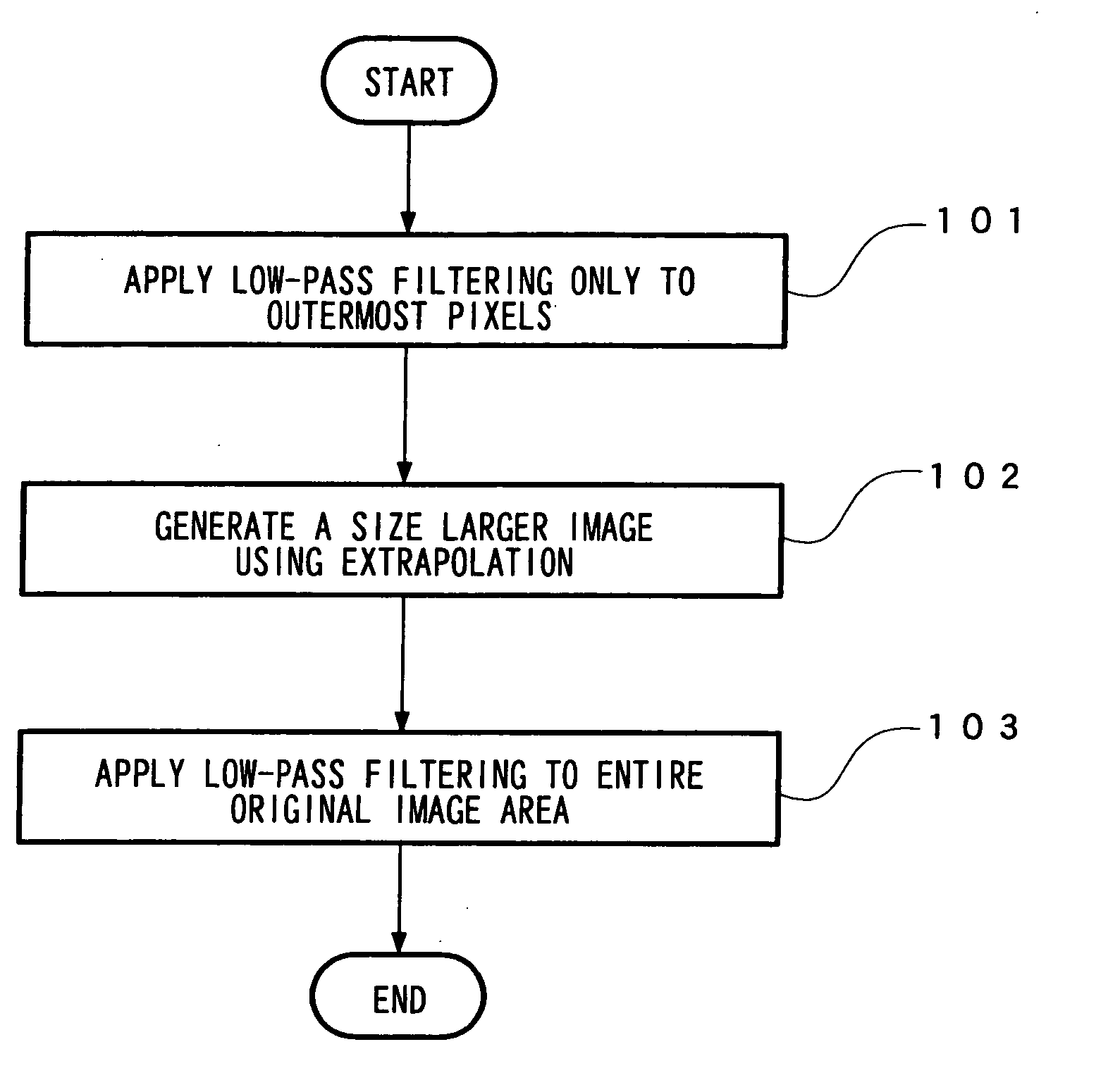
[0034] FIGS. 1 to 4A and 4B show a first embodiment of the present invention.

[0035]FIG. 1 shows a process flow of an image processing method according to the first embodiment.

[0036] At step 101, low-pass filtering is applied only to the pixels located in the borders of an original image P0 of interest.

[0037] At step 102, extrapolation is performed to generate an image of a size larger than the original image.

[0038] At step 103, low-pass filtering is applied to the entire original image to generate a desired low-pass-filtered image.

[0039] The above-stated procedure will be descried with respect to a more specific example.

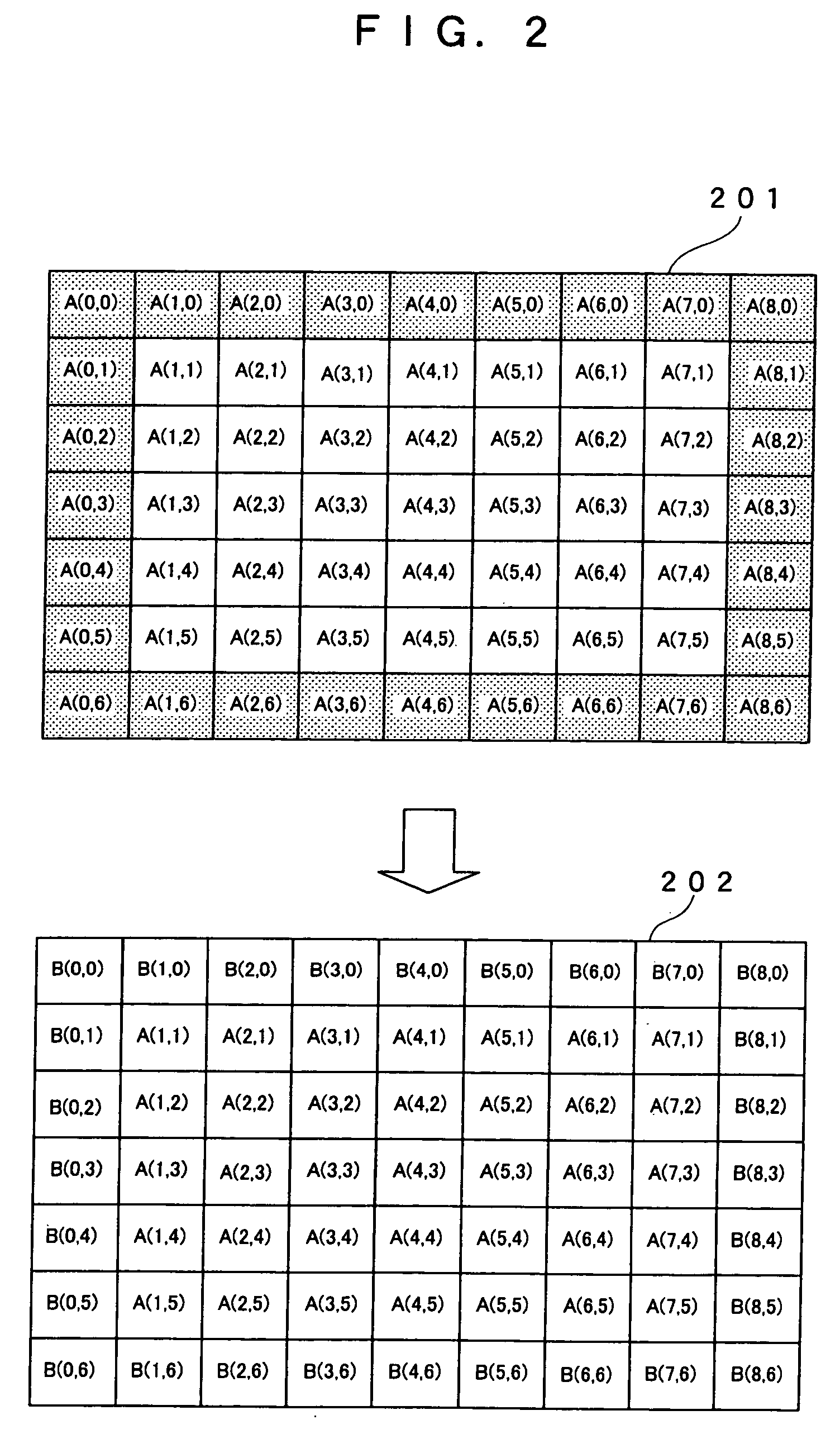
[0040]FIG. 2 shows conceptual diagrams showing the pixels in an original image and the pixels resulting from the processing at step 101. In FIG. 2, reference numeral 201 indicates the original monochrome image in which the pixels have brightness values in a 256-level gray scale, ranging from 0 to 255. For simplicity, it is assumed that the image is 9 pixels wid...

second embodiment

[0071]FIG. 5 shows an image processing apparatus performing image processing based on the image processing method described in the first embodiment. FIG. 9 shows a specific processing method performed by a defect detecting apparatus 502.

[0072] The image processing apparatus can be used for inspecting an image capturing device, such as a digital still camera or digital video camera, that uses a lens and a CCD (charge-coupled device). The following is a description of an exemplary application of the image processing apparatus as an inspection apparatus for inspecting lenses and CCDs in a digital still camera to be inspected for defects.

[0073] A camera 500 shown in FIG. 5, which is a digital still camera to be inspected, is used to capture an image of an inspection flat panel 501. The flat panel 501 is a solid-pail-color plate, painted gray for example. An original image P0 is an image of the flat plane 501 captured by the camera 500, and is digital image data. The original image P0 ...

third embodiment

[0090] FIGS. 6 to 8 show a fluorescent microscope image capturing apparatus performing image processing according to the image processing method of the first embodiment.

[0091] In FIG. 6, reference numeral 601 denotes an object to be observed, which is an image to be corrected and may be fluorescently dyed microbe cells, for example. When a laser beam from a laser light source 602 is reflected by a dichroic mirror and applied to the object to be observed 601, the fluorochrome in the object to be observed 601 is energized by the laser light to emit light with a particular wavelength. The light is captured by a CCD camera 604, digitized into image data, and processed in a host computer 605.

[0092] It is difficult to uniformly irradiate the observation surface with laser light emitted to the object to be observed 601. Typically, an illumination distribution is exhibited in which portions closer to the center are brighter than portions closer to the edges. If a fluorescent image energiz...


PUM


Abstract

Low-pass filtering is applied only to the borders of an original mage to reduce the noise in the borders of image, thereby preventing errors in extrapolation. Then, an extended region is provided around the image by extrapolation, thereby eliminating the need for border processing in the borders of the image when performing the final low-pass filtering. Finally, low-pass filtering is applied to the regions where the original image exists. Thus, a filtering effect can be obtained in which the regions nearer to the center of the image and the border regions of the image have the same characteristics.

Description

FIELD OF THE INVENTION [0001] The present invention relates to an image processing method which applies low-pass filtering to a captured image. BACKGROUND OF THE INVENTION [0002] Image processing methods which apply low-pass filtering to images typically obtain the average of pixels in a neighborhood of a pixel under consideration and use the average as a new brightness value of the pixel under consideration. Here, widening the area over which averaging is performed can enhance low-pass filtering and therefore remove local features in the image and provide a macro brightness distribution. [0003] Conventional image processing methods are used primarily for the purpose of removing noise. Accordingly, they are designed to preserve edge components of pixels to be processed as much as possible. For example, one method used is to select only pixels located in the direction in which a stronger correlation exists when neighborhood pixel averaging is performed (see for example Japanese Paten...

Claims


Application Information

Patent Timeline
Patent Type & Authority Applications(United States)
IPC IPC(8): G06K9/40
CPCG06T5/002G06T5/20G06T2207/20032G06T2207/20192
Inventor TAKARADA, SHINICHI
Owner PANASONIC CORP
Why Eureka
Try Eureka