
Catheter guidewire loading device and method

a catheter and guidewire technology, applied in the field of medical devices, can solve the problems of affecting the treatment of patients, and becoming difficult to insert the guidewire into the guidewire lumen of the catheter

Inactive Publication Date: 2006-05-04
CORDIS CORP
View PDF3 Cites 27 Cited by
  • Summary
  • Abstract
  • Description
  • Claims
  • Application Information

AI Technical Summary

Benefits of technology

[0008] Some catheters and guidewires are very flexible, particularly near their distal ends, to enhance their ability to follow more convoluted or tortuous anatomy. Some catheters and guidewires are very thin, especially those for use in narrow body passages including the vessels of the heart and brain, and may be on the order of a few millimeters or less. As medical products, catheters and their guidewire lumens as well as the guidewires, become more flexible and / or smaller in size, it may become challenging to insert the guidewire into a catheter's guidewire lumen. Also, some catheters have a distal guidewire port that is narrowed or tapered, which may hamper a physician when threading a guidewire into a catheter's guidewire lumen.
[0010] A loading device for facilitating the loading of a guidewire into a catheter lumen may be provided for use with catheters and guidewires. The loading device defines a passage having a first and second loading port. A portion of a catheter may be partially inserted into one of the loading ports, such that a catheter port communicates with the loading device passage. Then, one of the guidewire ends may be inserted into the other loading port. The guidewire may be more easily inserted through the loading device passage, into the catheter port, and thus into the catheter lumen.

Problems solved by technology

As medical products, catheters and their guidewire lumens as well as the guidewires, become more flexible and / or smaller in size, it may become challenging to insert the guidewire into a catheter's guidewire lumen.
Also, some catheters have a distal guidewire port that is narrowed or tapered, which may hamper a physician when threading a guidewire into a catheter's guidewire lumen.

Method used


Image

  • Catheter guidewire loading device and method
  • Catheter guidewire loading device and method
  • Catheter guidewire loading device and method

Examples


Embodiment Construction

[0023] The following description of the preferred embodiments of the present invention is merely illustrative in nature, and as such it does not limit in any way the present invention, its application, or uses. Numerous modifications may be made by those skilled in the art without departing from the true spirit and scope of the invention.

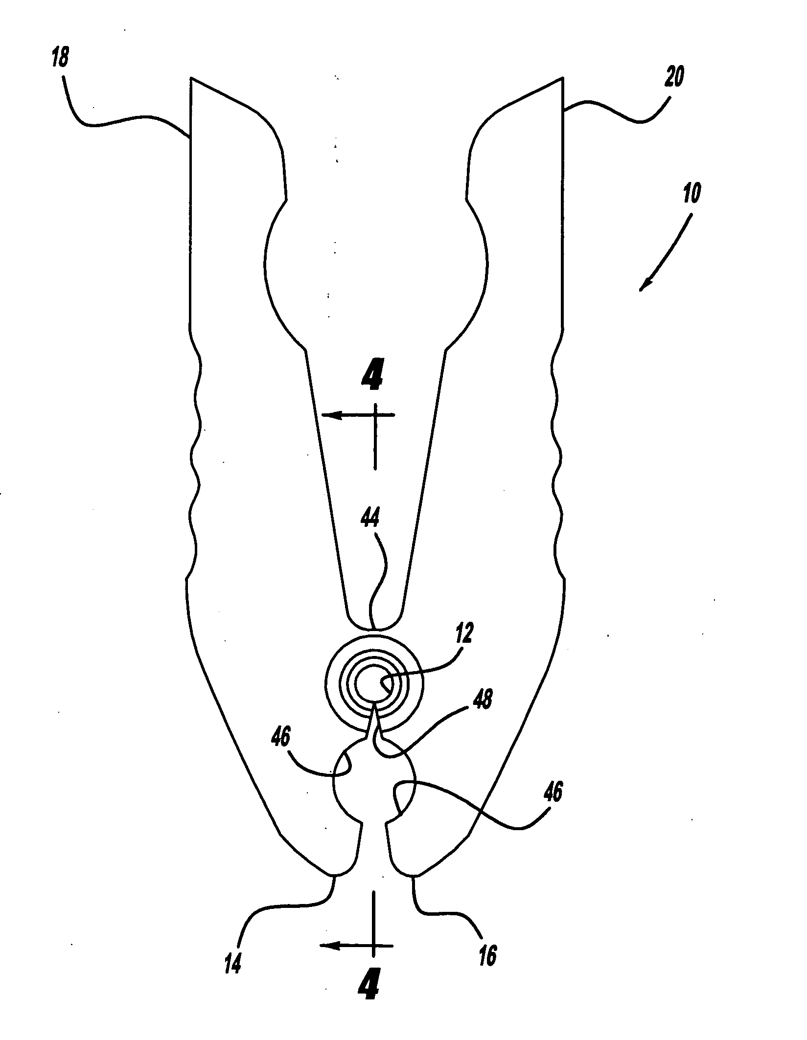
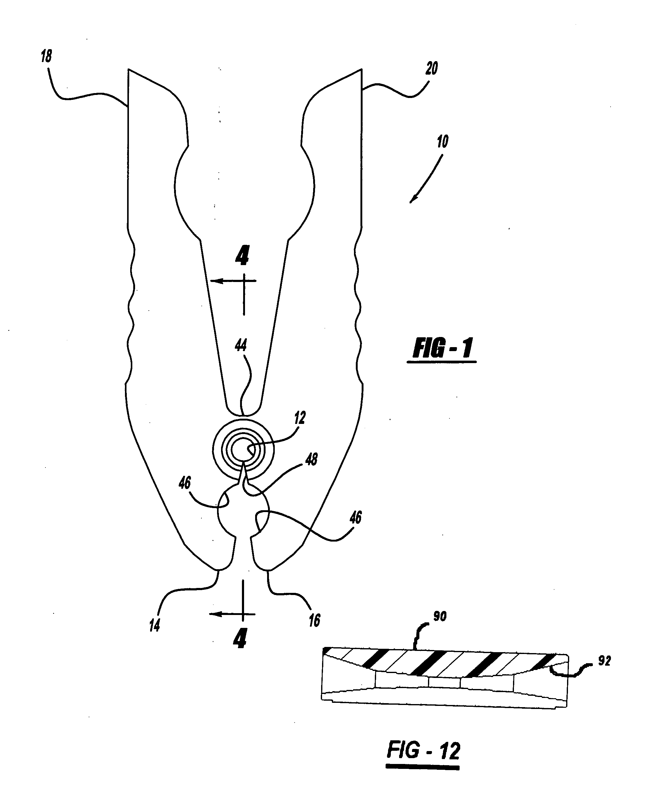
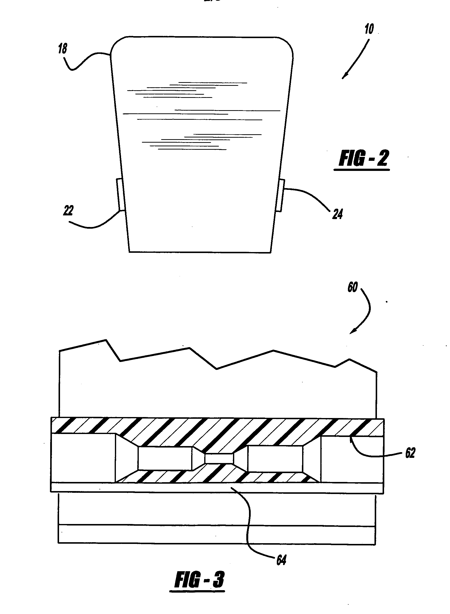
[0024] The drawings depict catheter guidewire loading devices along the lines of the present invention. FIGS. 1-5 show catheter guidewire loading devices in an arrangement having an optional additional feature, which is a clip for holding parts of catheter(s) and / or guidewire(s). FIGS. 6-12 show catheter guidewire loading devices alone, without additional features.

[0025] A catheter guidewire loading device 10 has a loading passage 12, a first and second clip portion 14 and 16, and a first and second handle portion 18 and 20. Loading passage 12 extends between a first and second end or loading port 22 and 24, has a first and second outer tubular se...


PUM


Abstract

A loading device for facilitating the loading of a guidewire into a lumen defined by a catheter. A catheter may have a shaft extending from a proximal end to a distal end, defining one or more lumens having one or more catheter ports. A guidewire has a flexible wire-like structure extending from a proximal end to a distal end. The guidewire loading device defines a passage having a first and second loading port. A portion of a catheter may be partially inserted into one of the loading ports, such that a catheter port communicates with the loading device passage. Then, one of the guidewire ends may be inserted into the other loading port. The guidewire may be more easily inserted through the loading device passage, into the catheter port, and thus into the catheter lumen.

Description

BACKGROUND AND SUMMARY OF THE INVENTION [0001] 1. Technical Background [0002] The present invention relates to medical devices, and more particularly to a device for facilitating the loading of a guidewire into a lumen defined by a catheter. [0003] 2. Discussion [0004] There are many different kinds and types of catheters, including for example balloon catheters, diagnostic catheters, guiding catheters, stent delivery system catheters, injection catheters, gene therapy catheters, electrophysiology catheters, therapeutic drug delivery catheters, ultrasound catheters, laser angioplasty catheters, etc. [0005] Catheters often have a flexible shaft extending between a proximal end and a distal end, and may define one or more tubular passages or “lumens” extending through part or all of the catheter shaft. Such lumens often have one or more openings, referred to as “ports.” When such a lumen is adapted to slidingly receive a guidewire, it is referred to as a “guidewire lumen,” and it will...

Claims


Application Information

Patent Timeline
Patent Type & Authority Applications(United States)
IPC IPC(8): A61M25/00
CPCA61M25/09041
Inventor VAN ERP, WILHELMUS PETRUS MARTINUS MARIASAKAGUCHI, DONNA
Owner CORDIS CORP
Learn More