
Emergency shower and eyewash station with temperature control

a technology of temperature control and emergency shower, which is applied in the direction of process and machine control, physical therapy, instruments, etc., can solve the problems of high cost of tanks, individual exposure, hypothermia or shock,

Inactive Publication Date: 2006-05-11
BRADFORD WHITE
View PDF15 Cites 14 Cited by
  • Summary
  • Abstract
  • Description
  • Claims
  • Application Information

AI Technical Summary

Benefits of technology

"The invention is an emergency water release device that includes heating elements, a shower, an eyewash, and a valve. The device is designed to prevent the water from becoming too hot and potentially causing damage. When the water temperature reaches a certain level, the device automatically shuts off one of the heating elements to reduce the flow of water. This allows the water to be dispersed away from both the shower and the eyewash in an equal amount. The heating elements are organized in two sets, one for the shower and one for the eyewash, which are connected in parallel. The device also includes a controller that can open a valve to mix in unheated water when the water temperature reaches a certain level. Overall, the device ensures that the water is always at a safe temperature and can be quickly released in case of an emergency."

Problems solved by technology

Emergency shower and eyewash stations are often used when there is a risk that an individual may be exposed to hazardous chemicals.
Hypothermia or shock can occur if one is required to stand under an emergency shower for an extended period of time under cold water, especially where the surrounding environment is cold.
However, such tanks are expensive and the duration of the shower is limited by the size of the tank.
However, such mixing valves are relatively costly.
However, such known designs do not prevent overshoot of water temperature upon reduction of a water flow rate from a high rate to a lower rate, as occurs, for example, when either the shower or the eyewash is shut off, or the shower is shut off and the eyewash is left on, etc.

Method used


Image

  • Emergency shower and eyewash station with temperature control
  • Emergency shower and eyewash station with temperature control
  • Emergency shower and eyewash station with temperature control

Examples


Embodiment Construction

[0014] It will be apparent to those skilled in the art, that is, to those who have knowledge or experience in this area of technology that many uses and design variations are possible for the emergency shower and eyewash station with temperature control disclosed herein. The following detailed discussion of various alternative and preferred features and embodiments will illustrate the general principles of the invention with reference to a heater for use with both a shower and an eyewash. Other embodiments suitable for other applications will be apparent to those skilled in the art given the benefit of this disclosure.

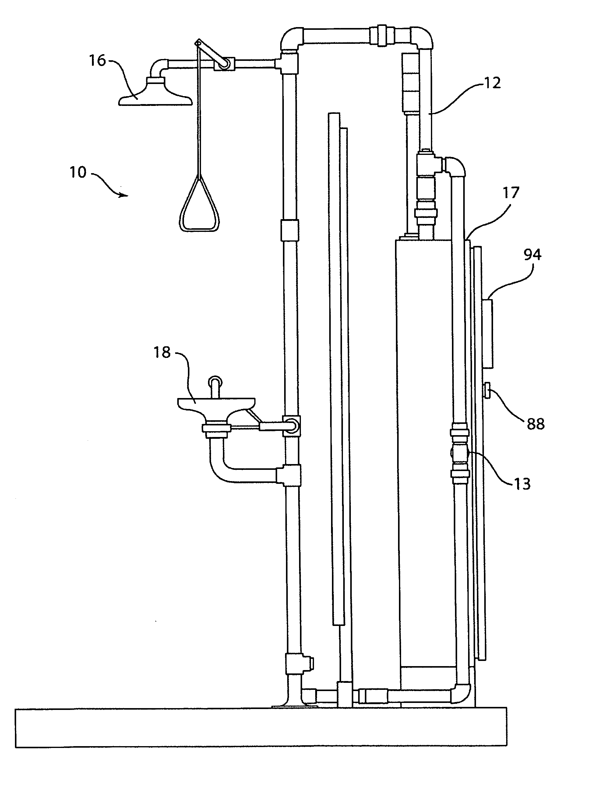
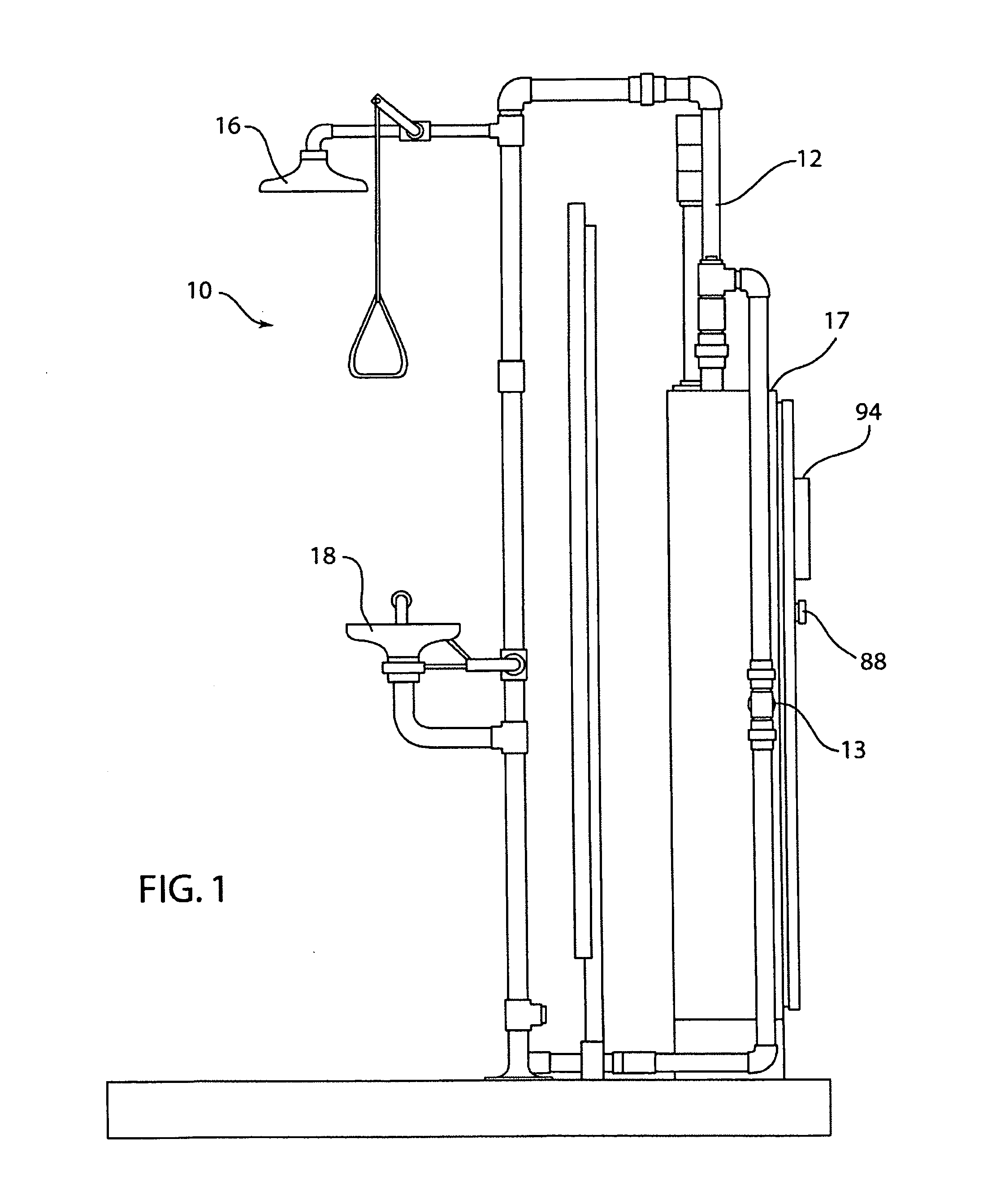
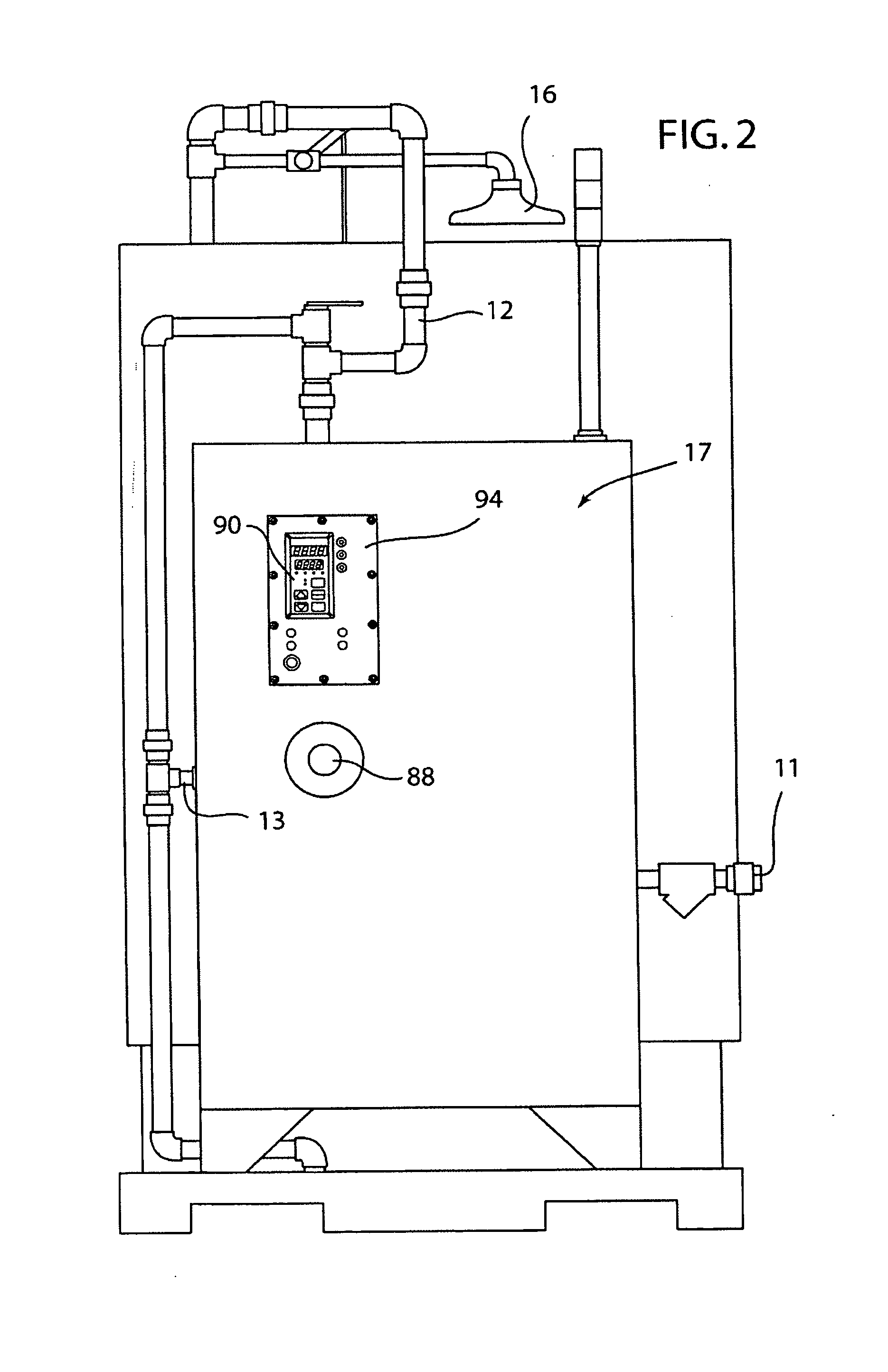
[0015] Referring now to the drawings, FIG. 1 shows an emergency shower and eyewash station 10 in accordance with a preferred embodiment. Water is heated by tankless water heater 17, and can be dispensed by either shower 16, eyewash 18 or both. Water flow is activated by the operator in a known manner. FIG. 2 shows the back of the station 10. The heater 17 is preferabl...


PUM


Abstract

An emergency water release device comprises heating elements adapted to heat water, a shower and an eyewash, a valve and a controller which sends a first signal to turn off at least one of the plurality of heating elements when a temperature of the water exceeds a predetermined limit, and when a flow rate of the water is reduced to a reduced flow rate, the valve opens so that water is dispersed away from both the shower and the eyewash in an amount equal to the difference between the flow rate and the reduced flow rate. The heating elements form a first set electrically connected in series which provides heat for water to be dispensed by the shower, a second set electrically connected in series which provides heat for water to be dispensed by the eyewash. The first and second set of heating elements can be connected in parallel. The controller may also be configured to send a signal to another valve to open so that unheated water is mixed with heated water.

Description

CROSS-REFERENCE TO RELATED APPLICATIONS [0001] This application is a divisional application of and claims priority from application Ser. No. 10 / 646,588 filed on Aug. 21, 2003, now U.S. Patent Publication US 2004 / 0039354 A1 published on Feb. 26, 2004, which claims priority benefit to U.S. Provisional Patent Application 60 / 405,002, filed on Aug. 21, 2002.FIELD OF THE INVENTION [0002] This invention relates to an apparatus for heating water, and more particularly, to an emergency shower and eyewash station with a temperature controller. BACKGROUND OF THE INVENTION [0003] Emergency shower and eyewash stations are often used when there is a risk that an individual may be exposed to hazardous chemicals. One who is exposed stands under the shower (or at the eyewash) for an extended period of time to flush away any such hazardous chemicals. Hypothermia or shock can occur if one is required to stand under an emergency shower for an extended period of time under cold water, especially where t...

Claims


Application Information

Patent Timeline
Patent Type & Authority Applications(United States)
IPC IPC(8): A61H33/00A61H33/04G05D23/13
CPCG05D23/1393
Inventor LUTZ, KENNETH E. II
Owner BRADFORD WHITE
Learn More