Tube roll for a paper machine and a method for manufacturing a tube roll

a technology of paper machine and tube roll, which is applied in the direction of manufacturing tools, portable power-driven tools, press sections, etc., to achieve the effects of improving loadability and vibration characteristics, reducing weight, and being more rigid

Inactive Publication Date: 2006-05-11
VALMET TECH INC
View PDF17 Cites 5 Cited by
  • Summary
  • Abstract
  • Description
  • Claims
  • Application Information

AI Technical Summary

Benefits of technology

[0009] The object of this invention is to provide a novel tube roll for a paper machine, which is lighter in weight, yet more rigid and having better loadability and vibration characteristics than heretofore. Another object of the invention is to provide a novel method for manufacturing a tube roll, which is faster and more efficient than heretofore and which can be used to manufacture tube rolls with varying characteristics. In the tube roll according to this invention, a material with essentially the same thickness can be used for both the cylinders and the core construction. At least the inner cylinder is made of sheet metal material. Unexpectedly the whole shell can be made of sheet metal material. This allows achieving a significant weight difference compared to conventional tube rolls. Also, the relation of the intrinsic mass of the tube roll to rigidity is better than heretofore. In addition, due to its construction and manufacturing method, the tube roll according to this invention is ready for use without machining. If required, a coating, which allows machining, is used to obtain desired tube roll surface characteristics. The roll head of the tube roll is also of a new construction utilizing axially symmetrical parts and sheet constructions. Furthermore, the core construction can be formed in many different ways and several different functions can be connected to the tube roll.

Problems solved by technology

Unexpectedly the whole shell can be made of sheet metal material.

Method used


Image

  • Tube roll for a paper machine and a method for manufacturing a tube roll
  • Tube roll for a paper machine and a method for manufacturing a tube roll
  • Tube roll for a paper machine and a method for manufacturing a tube roll

Examples


Embodiment Construction

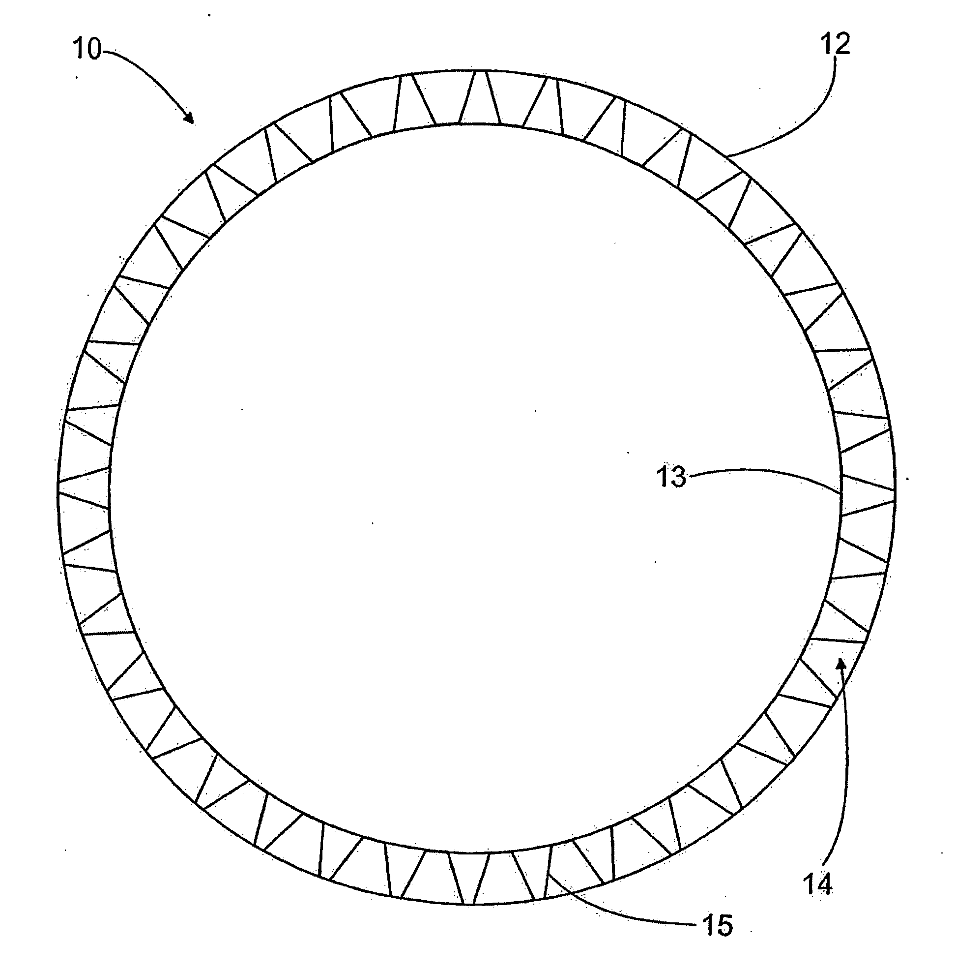
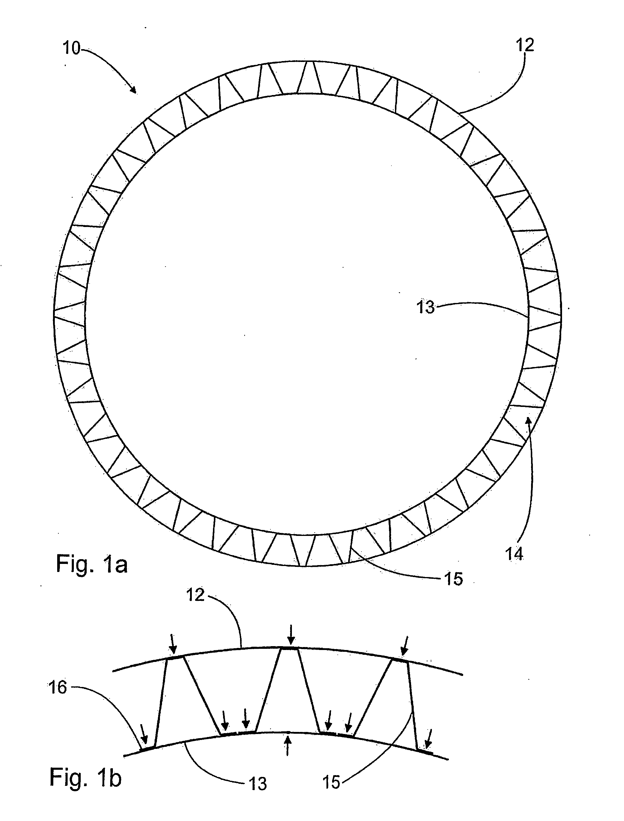
[0027]FIG. 1 is a cross-sectional view of the shell 10 of the tube roll according to the invention. Tube rolls are generally designed for paper machines, but they can as well be used in board machines and other similar forming machines. The basic components of the tube roll comprise a shell 10 and roll heads 11 at both shell ends for supporting the tube roll rotably to the paper machine. One embodiment of the roll head 11 is shown in FIG. 3. In addition, as shown in FIG. 1, the shell 10 has two metal cylinders 12 and 13, adapted coaxially at an interval of each other. A core construction 14, located between the cylinders 12 and 13 and attached to both of the cylinders 12 and 13, is used for supporting the cylinders 12 and 13.

[0028] According to the invention, at least the inner cylinder is unexpectedly made of a sheet metal material having a thickness of 1-5 mm, more preferably 2-4 mm. In a tube roll that does not form a nip with the counter roll the outer cylinder is also preferab...


PUM

PropertyMeasurementUnit
thicknessaaaaaaaaaa
diameteraaaaaaaaaa
wall thicknessaaaaaaaaaa

Abstract

A tube roll for a paper machine has a shell (10) and roll heads (11) for supporting the tube roll rotably to the paper machine. The shell (10) has two metal cylinders (12, 13) adapted coaxially at an interval of each other. Between the cylinders (12, 13) there is additionally a core construction (14) attached to both of the cylinders (12, 13). Each roll head (11) is attached to both of the cylinders, of which at least the inner cylinder (13) is made of a sheet metal material. The invention also relates to a method for manufacturing a tube roll.

Description

BACKGROUND OF THE INVENTION [0001] This invention relates to a tube roll for a paper machine, in which the tube roll includes [0002] a shell and roll heads at both of its ends for supporting the tube roll rotably to a paper machine, [0003] two metallic cylinders in the shell, adapted coaxially at an interval of each other, and [0004] between the cylinders, a core construction attached to both cylinders. The invention also relates to a method for manufacturing a tube roll. [0005] So-called tube rolls are used both in paper machines and board machines. A tube roll has a hollow interior and its shell is tubular. Compared to a solid roll, tube rolls are primarily used in nipless positions due to their lightweight but hollow construction. That is, tube rolls are separate without contacting another roll. Such positions include for example paper rolls and lead rolls as wells as extraction rolls in a calender. Roll heads are additionally mounted at the shell ends by means of which the tube ...

Claims


Application Information

Patent Timeline
Patent Type & Authority Applications(United States)
IPC IPC(8): B21D53/00F16C13/00D21F1/40D21F3/08D21G1/02
CPCD21F1/40D21F3/08Y10T29/49549D21G1/0246D21G1/02F16C13/00
Inventor KURKINEN, LEOVANNINEN, RAMILANNES, PETTERIPITKANEN, TATUHOLOPAINEN, KARI
Owner VALMET TECH INC
Why Eureka
Try Eureka