Determination of borehole azimuth and the azimuthal dependence of borehole parameters

a technology of borehole and parameter, which is applied in the field of subterranean borehole logging methods, can solve the problems of image distortion, tool and borehole azimuth assumption being not typically valid for lwd applications, and the eccentricity of lwd tools in the borehole may change with time, so as to improve the usefulness of borehole images, minimize misregistration errors, and improve image resolution and noise rejection.

Active Publication Date: 2006-05-11
SCHLUMBERGER TECH CORP
View PDF28 Cites 41 Cited by
  • Summary
  • Abstract
  • Description
  • Claims
  • Application Information

AI Technical Summary

Benefits of technology

[0006] Exemplary embodiments of the present invention may advantageously provide several technical advantages. For example, embodiments of this invention enable borehole azimuths to be determined for a borehole having substantially any shape. Furthermore, in certain exemplary embodiments, borehole azimuths, lateral displacement vector(s), and a borehole parameter vector defining the shape and orientation of the borehole may be determined simultaneously. Moreover, in certain exemplary embodiments, such parameters may be determined via conventional ultrasonic standoff measurements and convent

Problems solved by technology

However, in LWD applications, an LWD tool is not typically centered in the borehole (i.e., the longitudinal axes of the tool and the borehole are not coincident) since the tool is coupled to a drill string.
It is well known that a drill string is often substantially free to translate laterally in the borehole (e.g., during drillin

Method used


Image

  • Determination of borehole azimuth and the azimuthal dependence of borehole parameters
  • Determination of borehole azimuth and the azimuthal dependence of borehole parameters
  • Determination of borehole azimuth and the azimuthal dependence of borehole parameters

Examples


Embodiment Construction

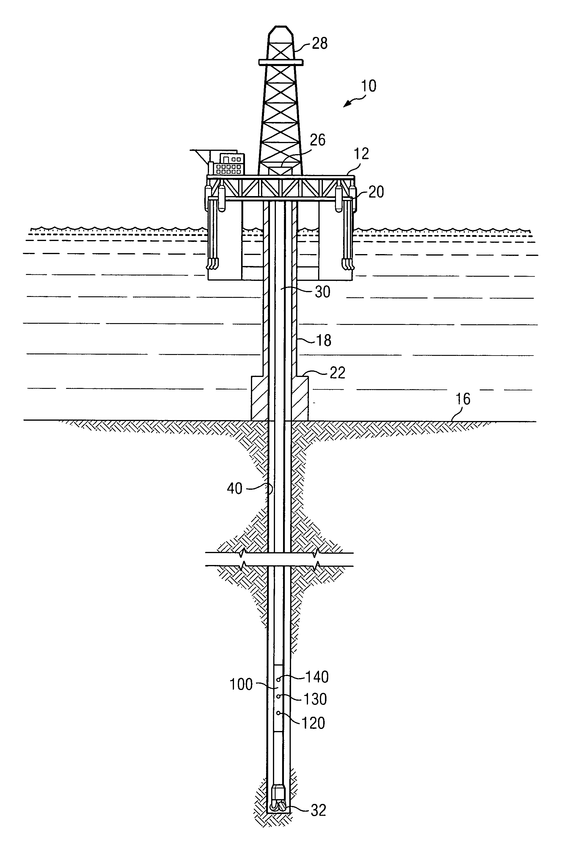
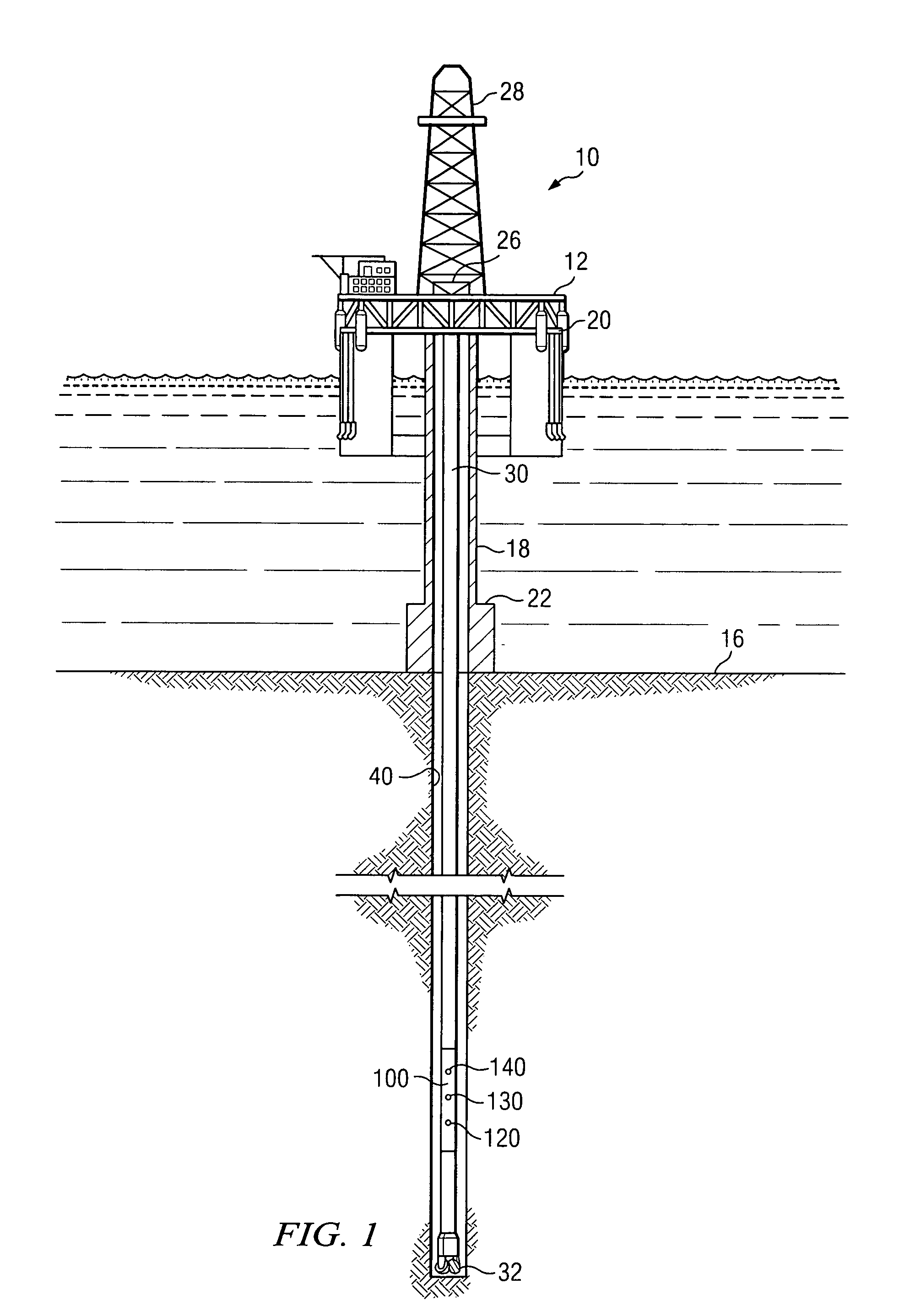
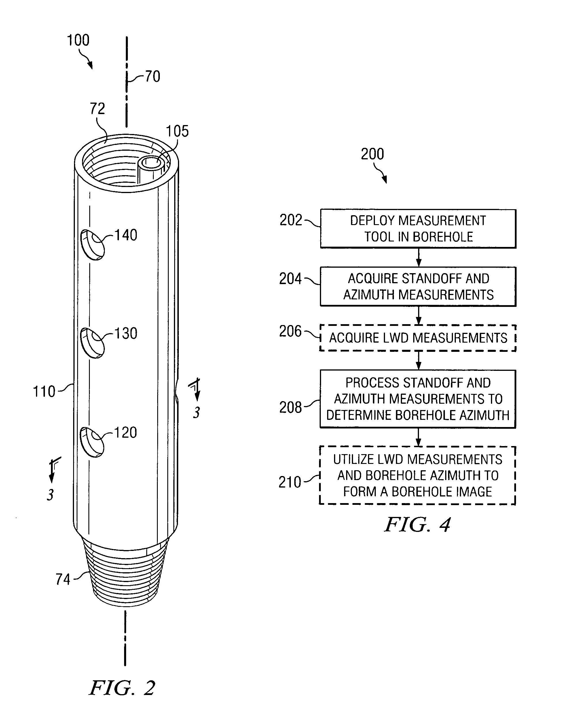
[0019] With reference to FIGS. 1 through 3, it will be understood that features or aspects of the embodiments illustrated may be shown from various views. Where such features or aspects are common to particular views, they are labeled using the same reference numeral. Thus, a feature or aspect labeled with a particular reference numeral on one view in FIGS. 1 through 3 may be described herein with respect to that reference numeral shown on other views.

[0020]FIG. 1 schematically illustrates one exemplary embodiment of a downhole tool 100 in use in an offshore oil or gas drilling assembly, generally denoted 10. In FIG. 1, a semisubmersible drilling platform 12 is positioned over an oil or gas formation (not shown) disposed below the sea floor 16. A subsea conduit 18 extends from deck 20 of platform 12 to a wellhead installation 22. The platform may include a derrick 26 and a hoisting apparatus 28 for raising and lowering the drill string 30, which, as shown, extends into borehole 40 ...


PUM


Abstract

A method for determining a borehole azimuth in a borehole is disclosed. In one exemplary embodiment, the method includes acquiring at least one standoff measurement and a tool azimuth measurement at substantially the same time. Such measurements are then processed, along with a lateral displacement vector of the downhole tool upon which the sensors are deployed in the borehole, to determine the borehole azimuth. The computed borehole azimuths may be advantageously correlated with logging sensor data to form a borehole image, for example, by convolving the correlated logging sensor data with a window function. As such, exemplary embodiments of this invention may provide for superior image resolution and noise rejection as compared to prior art LWD imaging techniques.

Description

FIELD OF THE INVENTION [0001] The present invention relates generally to a method for logging a subterranean borehole. More specifically, this invention relates to processing a standoff measurement and a tool azimuth measurement to determine a borehole azimuth and correlating the borehole azimuth with logging while drilling sensor measurements to estimate the azimuthal dependence of a borehole parameter. BACKGROUND OF THE INVENTION [0002] Wireline and logging while drilling (LWD) tools are often used to measure physical properties of the formations through which a borehole traverses. Such logging techniques include, for example, natural gamma ray, spectral density, neutron density, inductive and galvanic resistivity, acoustic velocity, acoustic calliper, downhole pressure, and the like. Formations having recoverable hydrocarbons typically include certain well-known physical properties, for example, resistivity, porosity (density), and acoustic velocity values in a certain range. In ...

Claims


Application Information

Patent Timeline
IPC IPC(8): E21B47/022
CPCE21B47/022
Inventor HAUGLAND, S. MARK
Owner SCHLUMBERGER TECH CORP
Why Eureka
Try Eureka