Liquid-cooling device for internal combustion engine

Inactive Publication Date: 2006-05-11
DENSO CORP
View PDF6 Cites 23 Cited by
  • Summary
  • Abstract
  • Description
  • Claims
  • Application Information

AI Technical Summary

Benefits of technology

[0008] The present invention is made in view of the above problems. Thus, it is an object of the present invention to provide a liquid-cooli

Problems solved by technology

However, such operation of the pump is not optimum for cooling the engine.
As a result, an excessive amount of the cooling water flows through the engine at a low load engine operation, such as an ordinary running of a vehicle, causing a problem that the excessive amount of the cooling water may deteriorate a warming-up performance for the engine.
Furthermore, since the cooling water flows in an engine cooling water circuit having a high flow resistance, due to the hole formed in the gask

Method used


Image

  • Liquid-cooling device for internal combustion engine
  • Liquid-cooling device for internal combustion engine
  • Liquid-cooling device for internal combustion engine

Examples


first embodiment

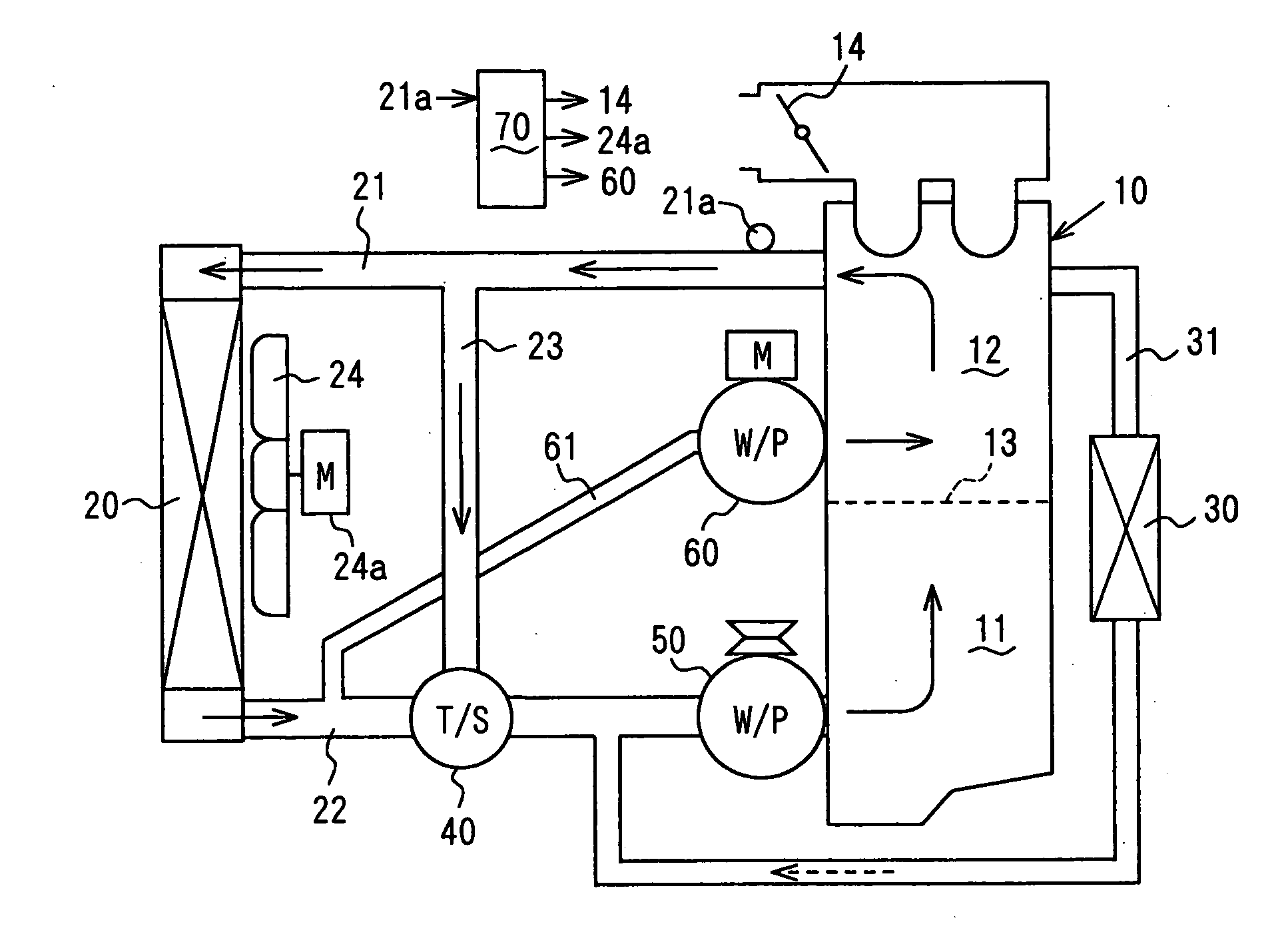
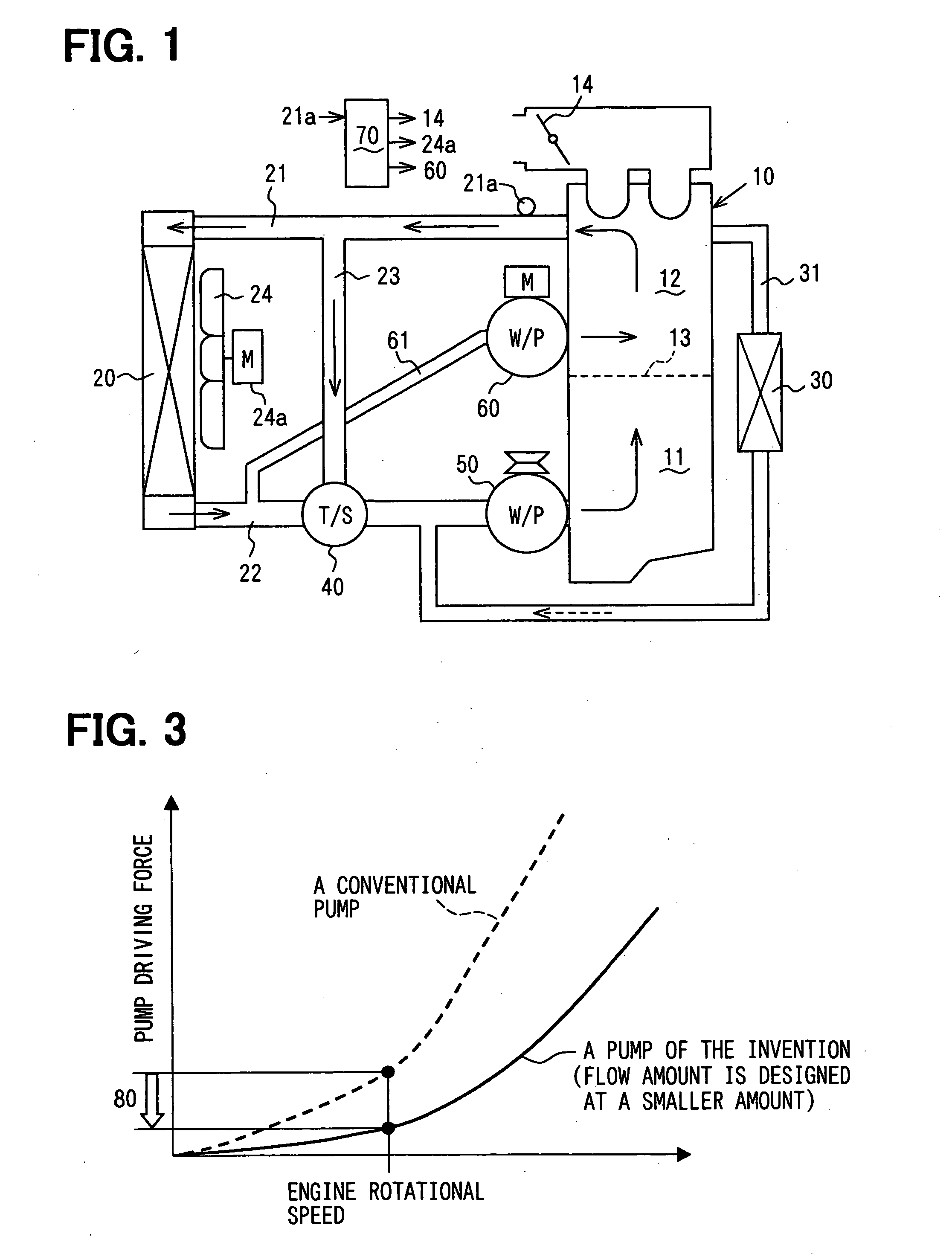
[0023] As shown in FIG. 1, in a liquid-cooling system for a vehicle of the first embodiment, a liquid-cooling type internal combustion engine 10 and a radiator 20 are connected with each other through an inflow path 21 and a backflow path 22. The radiator 20 is for performing heat exchange between external air and cooling water for cooling the engine 10.

[0024] Specifically, an upstream end of the inflow path 21 is connected with a cylinder head 12 of the engine 10 and the other end (namely a downstream end) is connected with an entrance of the radiator 20. In addition, an upstream end of the backflow path 22 is connected with an exit of the radiator 20 and the other end (namely a downstream end) is connected with a cylinder block 11 of the engine 10.

[0025] When cooling water is heated up at the expense of cooling down the engine 10, it goes through the inflow path 21 and enters the radiator. In the radiator 20, the heat exchange cools down the cooling water. Then the cooling water...

second embodiment

[0058] The liquid-cooling device of the second embodiment shown in FIG. 5 differs from that of the first embodiment in that a water storage tank 25 is installed at a point where the head cooling path 61 diverges from the backflow path 22. Since the tank 25 stores the cooling water from the radiator 20, the second pump 60 can supply the stored cooling water to the cylinder head 12 with a quick response.

[0059] In the case that a volume of the tank 25 is designed to be large enough to supply the cooling water to the cylinder head 12, the tank can store the sufficiently cooled water, when the temperature of cooling water to the cylinder block 11 is controlled at the relatively high value and thereby the flow amount from the radiator 20 to the first pump 50 is reduced. Therefore, the second pump 60 can supply the large amount of the sufficiently cooled water to the cylinder head 12.

third embodiment

[0060] The liquid-cooling device of the third embodiment shown in FIG. 6 differs from that of the second embodiment in three points described below. The first difference is that the first pump 50 in the second embodiment is replaced by an electrically operated pump 500 which is controlled by the engine controller 70 independently of the engine operation. Thus, the liquid-cooling device supplies the cooling water in a more appropriate manner.

[0061] The second difference is that a lower tank 20b of the radiator 20 and the water storage tank 25 are made as one unit. Thus, the structure of the liquid-cooling device of the third embodiment becomes simpler, and manufacturing cost of the liquid-cooling device is reduced.

[0062] The third difference is that the second pump 60 is installed at the lower tank 20b, that is, the tank 25. Thus, the second pump 60 becomes more stable against vibrations of the liquid-cooling device. Therefore, the second pump 60 can be made smaller and at a lower ...


PUM


Abstract

A head cooling path diverges from a backflow path at a position between a radiator and a thermostat and is connected with a cylinder head of an engine by bypassing a cylinder block of the engine. A pump circulates the cooling water through the head cooling path, to the cylinder head, when the engine is operated at a high load and/or a vehicle is in a rapid acceleration, so that sufficiently cooled cooling water is supplied directly to the cylinder head.

Description

CROSS REFERENCE TO RELATED APPLICATION [0001] This application is based on and incorporates herein by reference Japanese patent application No. 2004-328126 filed on Nov. 11, 2004. FIELD OF THE INVENTION [0002] The present invention relates to a liquid-cooling device for cooling down an internal combustion engine such as an engine of a vehicle. In particular, the present invention relates to a cooling device for the engine, in which an electrically operated pump is additionally provided so that engine cooling water is supplied to the engine independently from engine rotational speed. BACKGROUND OF THE INVENTION [0003]FIG. 7 is a graph showing a relation between an amount of flow of cooling water and an engine rotational speed for a conventional liquid-cooling device. Conventionally, a mechanically operated pump for circulating the cooling water is operated by receiving a driving force from the engine. Therefore, the amount of the flow of the cooling water is proportional to the rotat...

Claims


Application Information

Patent Timeline
IPC IPC(8): F01P7/14F01P3/22F01P5/10
CPCF01P3/02F01P7/165F01P7/167F01P2003/021F01P2003/024F01P2005/105F01P2005/125F01P2060/08
Inventor TAKAHASHI, EIZO
Owner DENSO CORP
Why Eureka
Try Eureka