Method and apparatus for slant drilling

a technology of slant rigs and slanting, which is applied in the direction of drilling rods, drilling pipes, cranes, etc., can solve the problems of inability to slant rigs at inability to slant rigs to achieve virtually any angle between 0 and 90 degrees, and suffer from a number of shortcomings. , to achieve the effect of reducing personnel, improving safety and reducing costs

Inactive Publication Date: 2006-05-11
LANDRY HAROLD WAYNE
View PDF5 Cites 16 Cited by
  • Summary
  • Abstract
  • Description
  • Claims
  • Application Information

AI Technical Summary

Benefits of technology

[0013] In the preferred embodiment of the present invention, an automated pipe handling apparatus is also provided which permits efficient transfer of pipe sections from said derrick (and jack apparatus) to a truck, pipe rack or other storage facility. As a result of such automated pipe handling apparatus, the labor requirement associated with loading and unloading pipe is substantially less than labor requirements associated with conventional drilling rigs. Safety is also greatly improved as a result of such automated pipe handling apparatus since it is generally not necessary to position personnel within the derrick. Additionally, less personnel are required on the rig floor compared to standard rigs.
[0014] The slant rig of the present invention can be trailer-mounted for easy transportation to and from well sites using standard trucks. Similarly, the various components of said rig including, without limitation, mud tanks, pumps, control equipment and crew quarters, can also be skid, track truck-mounted. As a result, said components can be

Problems solved by technology

However, such existing rigs cannot slant at virtually any angle between 0 and 90 degrees—that is, from nearly horizontal to vertical.
Such conventional slant rigs suffer from a number of shortcomings.
Most notably, such rigs do not have lif

Method used


Image

  • Method and apparatus for slant drilling
  • Method and apparatus for slant drilling
  • Method and apparatus for slant drilling

Examples


Embodiment Construction

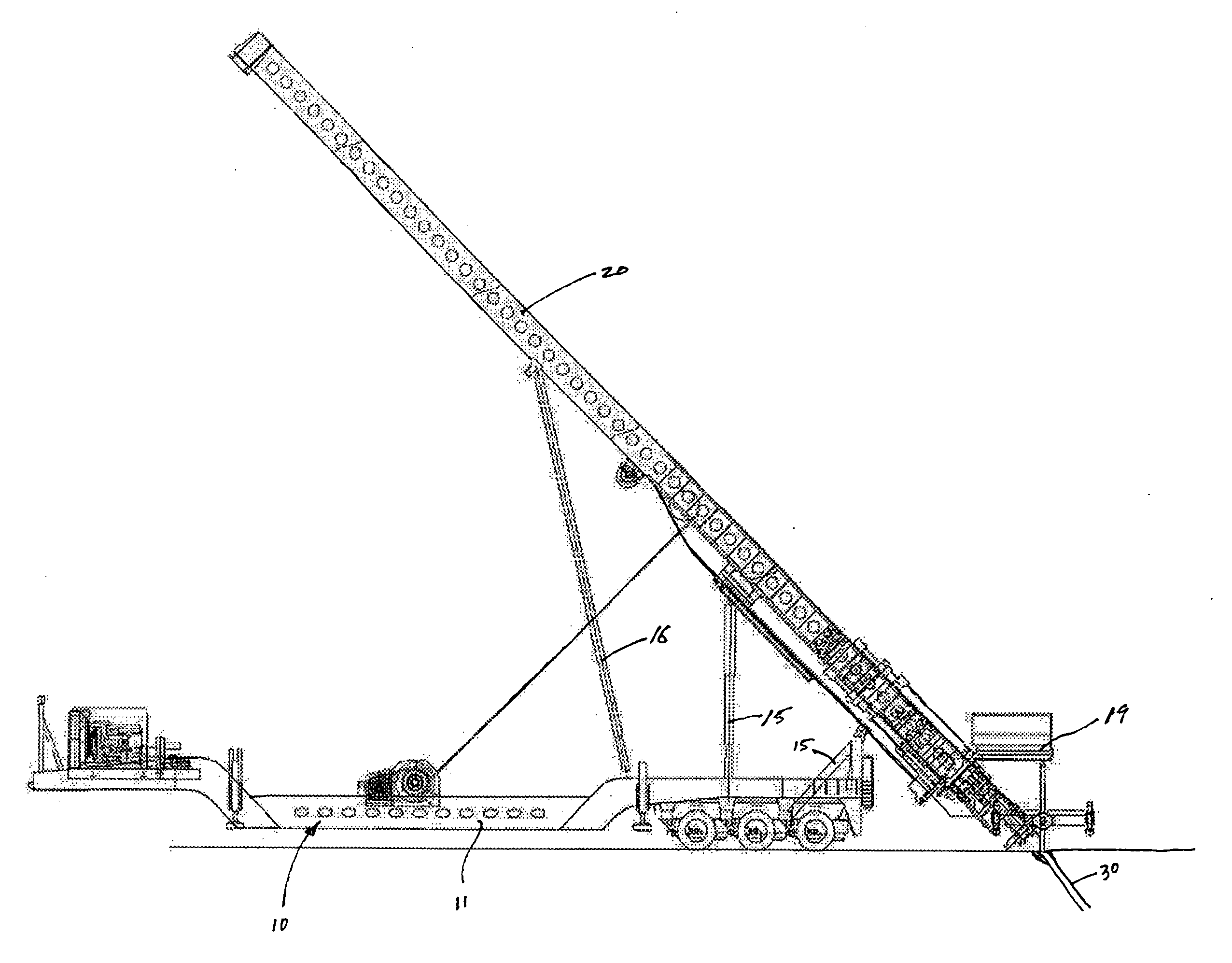
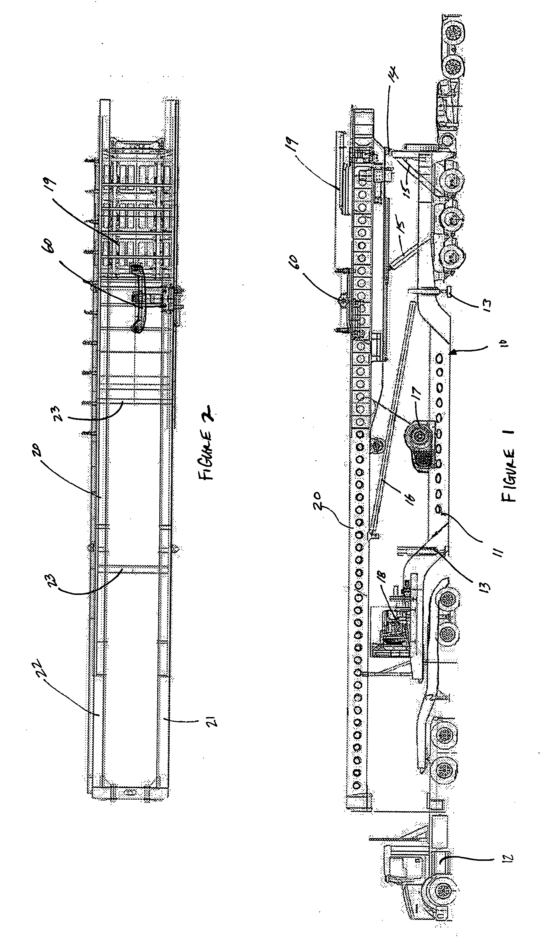
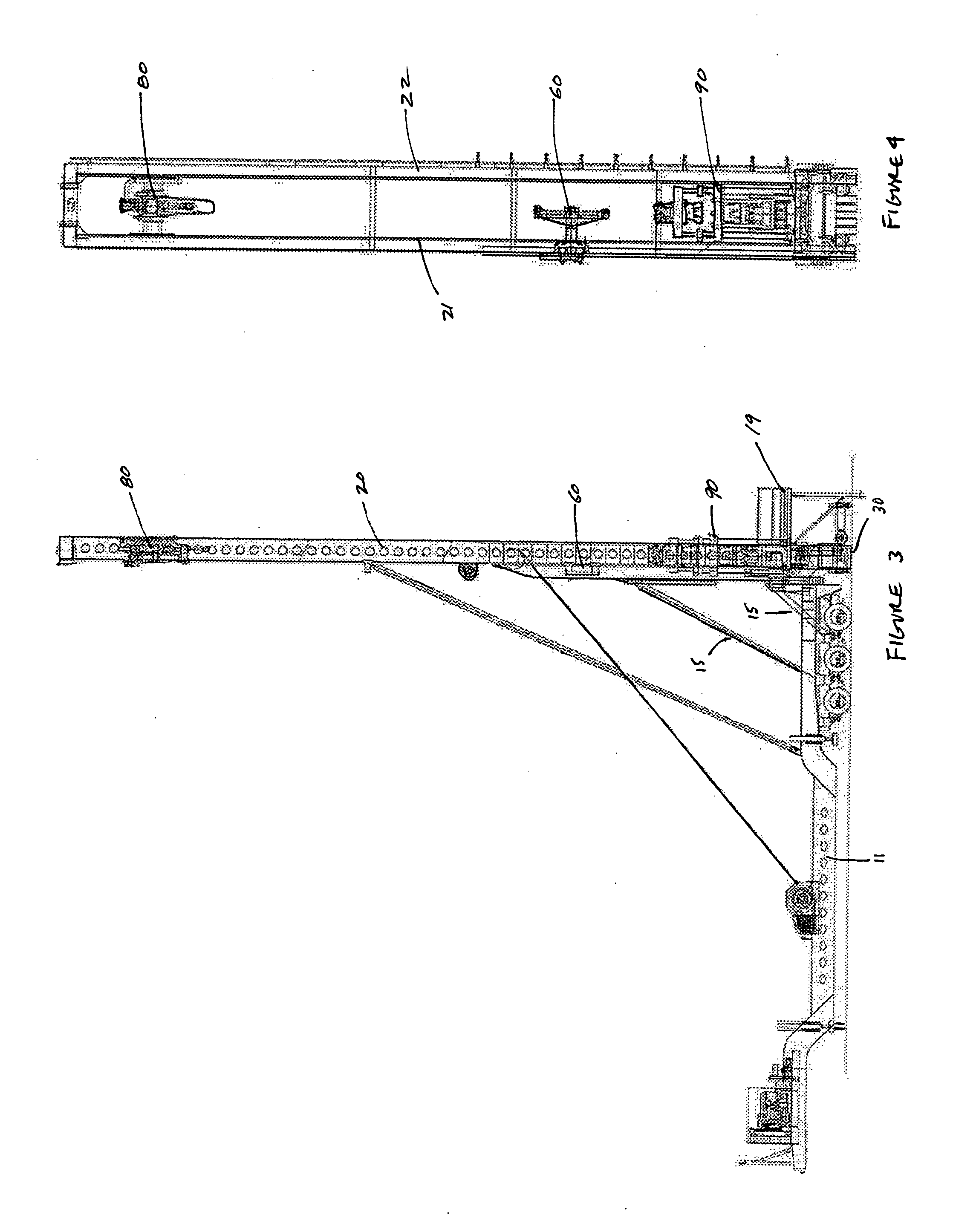
[0025] Referring to the drawings, FIG. 1 depicts a side view of slant rig 10 of the present invention. In the preferred embodiment of the present invention, slant rig 10 is mounted on trailer 11. Trailer 11 can in turn be attached to, and pulled by, tractor 12. In this configuration, slant rig 10 can be easily and conveniently transported to and from desired locations. Derrick 20 is mounted on trailer 11. Adjustable trailer pedestals 13 can be used to provide additional support and stability to trailer 11, especially when said trailer 11 is rigged up at a desired work site.

[0026] In the preferred embodiment, derrick 20 can be tilted about a horizontal pivot axis passing through pin 14. During transportation of slant rig 10, derrick 20 is frequently in a collapsed or horizontal position on trailer 11. Hydraulic cylinders 15 can be used to lift derrick 20 and thereby tilt said derrick about pivot pin 14. More specifically, hydraulic cylinders 15 can be extended or collapsed to positi...


PUM


Abstract

A rig for drilling wells or holes at virtually any angle, from nearly horizontal to vertical, has a trailer mounted derrick which can be tilted to a desired angle, a top drive unit slidably mounted within such derrick and a hydraulic jacking apparatus. An automated pipe handling apparatus permits efficient transfer of pipe sections from the derrick to a truck, pipe rack or other storage facility.

Description

CROSS REFERENCES TO RELATED APPLICATIONS [0001] NONE STATEMENTS AS TO RIGHTS TO INVENTIONS MADE UNDER FEDERALLY SPONSORED RESEARCH AND DEVELOPMENT [0002] NONE BACKGROUND OF THE INVENTION [0003] 1. Field of the Invention [0004] The present invention relates to a rig which can efficiently and economically drill wells at virtually any angle, from nearly horizontal to vertical. More particularly still, the present invention relates to a rig which can efficiently and economically drill wells, including deviated or high angle wells, with less pipe stress and impact on the surrounding environment than conventional drilling rigs. [0005] 2. Description of the Prior Art [0006] Many wells, such as oil and / or gas wells are drilled vertically into the earth's crust. However, it is frequently beneficial to drill wells at an angle from vertical. Such “deviated” wells are often drilled from a single surface location towards one or more subsurface targets which are situated some lateral distance awa...

Claims


Application Information

Patent Timeline
IPC IPC(8): E21B19/20B66C23/62
CPCE21B15/04E21B19/14
Inventor LANDRY, HAROLD WAYNE
Owner LANDRY HAROLD WAYNE
Why Eureka
Try Eureka