
Detecting irises and pupils in images of humans

Active Publication Date: 2006-05-11
MONUMENT PEAK VENTURES LLC
View PDF20 Cites 126 Cited by
  • Summary
  • Abstract
  • Description
  • Claims
  • Application Information

AI Technical Summary

Benefits of technology

[0017] It is an advantageous effect of the invention that an improved eye detection methods and systems are provided, in which iris boundaries can be detected with relatively good efficient and moderate computing resources. It is a further advantageous effect of the invention that an improved eye detection methods and systems are provided, in which redeye defect information is usable, but not mandatory.
that an improved eye detection methods and systems are provided, in which iris boundaries can be detected with relatively good efficient and moderate computing resources. It is a further advantageous effect of the invention that an improved eye detection methods and systems are provided, in which redeye defect information is usable, but not mandatory.

Problems solved by technology

This is suitable for some purposes, but deleterious for others.
Redeye is commonly a problem in cameras that have a flash unit located close to the taking lens.
This approach is effective, but labor-intensive and slow.
Automated detection of redeye pixels can be faster, but it is often the case that the boundary of a redeye defect is not well defined.
This is also a problem in a semi-automated approach, in which a user indicates an eye location by setting a single point.
When coupled with defect correction, these misclassifications can produce objectionable artifacts.
As a result, a portion of the human subject's pupil can still appear objectionably red.
As a result, a non-pupil portion of the human face, such as the eyelid, can be modified by the color correction normally applied to redeye pixels, resulting in a very objectionable artifact.
If such a blending filter is of uniform size for all human images, then some (typically relatively small) human faces having redeye defects may appear over smoothed, with objectionable blurriness.
This may be effective, but it is another labor-intensive and slow procedure.
The above approaches tend to have limited applicability or place large demands on processing resources.

Method used


Image

  • Detecting irises and pupils in images of humans
  • Detecting irises and pupils in images of humans
  • Detecting irises and pupils in images of humans

Examples


Embodiment Construction

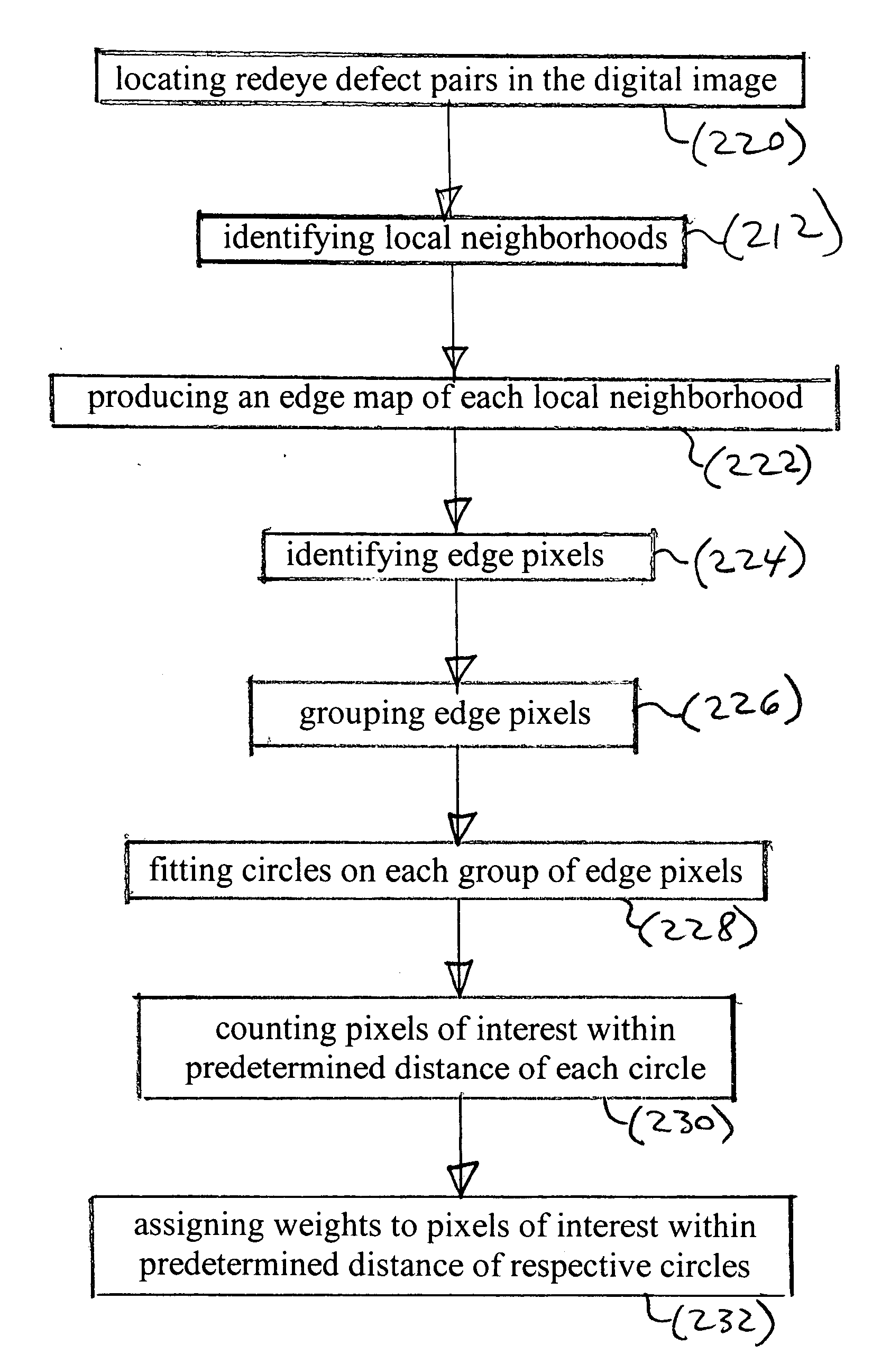
[0036] In the following eye detection methods, eye features are detected in a digital image. The eye features are iris-sclera borders or pupil-iris borders or both. For convenience, the following discussion is directed primarily to detection of iris-sclera borders. It will be understood that pupil-iris borders can be detected in a comparable manner and that both borders can be detected for the same eye, either independently or using the first border detected to limit the possible locations of the second of the two borders.

[0037] In the following description, some embodiments of the present invention will be described as software programs. Those skilled in the art will readily recognize that the equivalent of such software can also be constructed in hardware. Because image manipulation algorithms and systems are well known, the present description will be directed in particular to algorithms and systems forming part of, or cooperating more directly with, the method in accordance wit...


PUM


Abstract

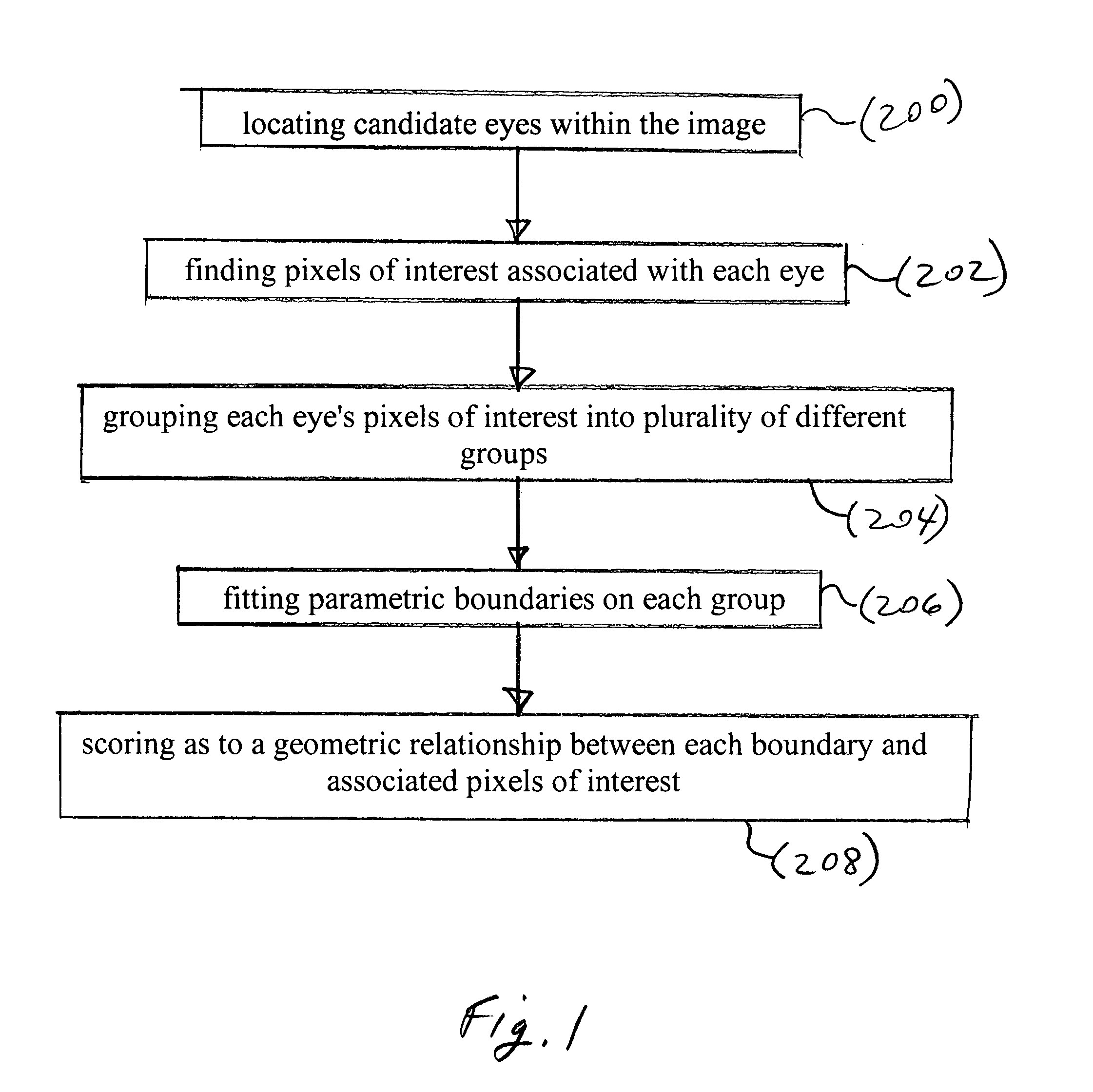
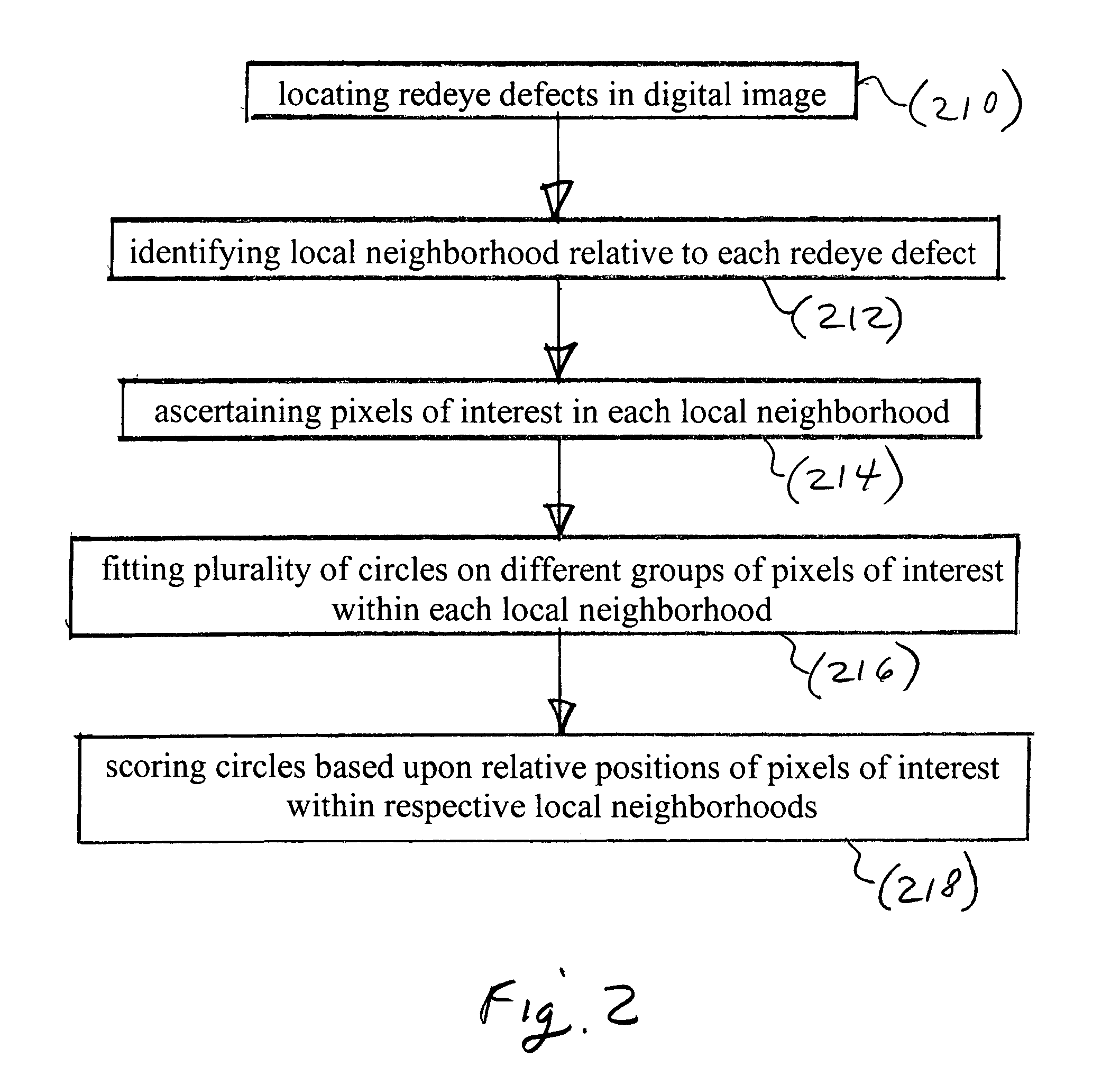
In an eye detection method, a plurality of candidate eyes are located within a digital image. Pixels of interest having a predetermined characteristic and a predetermined association to respective eyes are found. Pixels of interest associated with each eye are grouped. Parametric boundaries are fit on each of the groups to define a plurality of detected eye features. The boundaries have a predefined uniform shape and a size matched to a respective group. Each of the detected eye features is scored as to a geometric relationship between the respective boundary and pixels of interest associated with the respective eye to provide eye feature scores.

Description

CROSS REFERENCE TO RELATED APPLICATIONS [0001] Reference is made to commonly assigned, co-pending U.S. patent application Ser. No. 10 / 792,079, [Attorney Docket No. DOCKET 87517RLW], filed Mar. 3, 2004, entitled: CORRECTION OF REDEYE DEFECTS IN IMAGES OF HUMANS”, in the name(s) of Andrew C. Gallagher and Jay S. Schildkraut.FIELD OF THE INVENTION [0002] The invention relates to image processing and more particularly relates to detection of human irises and pupils, especially for correction of redeye defects in images of humans having redeye. BACKGROUND OF THE INVENTION [0003] Numerous digital image processing procedures, such as identification of persons in digital photographs and redeye correction procedures, find human eyes in digital images. In many of these procedures, the located position of human eyes is approximate. This is suitable for some purposes, but deleterious for others. [0004] Redeye correction can be improved by accurate determination of eye locations. The term “redey...

Claims


Application Information

Patent Timeline
IPC IPC(8): G06K9/00G06K9/40G06K9/46
CPCG06K9/0061G06K2009/00322G06T7/0083G06T2207/30201G06T2207/30216G06T7/12G06V40/178G06V40/193
Inventor GALLAGHER, ANDREW C.
Owner MONUMENT PEAK VENTURES LLC
Learn More