Magnetic resonance imaging system for non-contrast MRA and magnetic resonance signal acquisition method employed by the same

a magnetic resonance imaging and non-contrast technology, applied in the field of magnetic resonance imaging systems for medical use and magnetic resonance signal acquisition methods, can solve the problems of large mental and physical burden on subjects, inability to administer contrast medium to subjects, and high cost of such examinations, so as to reduce patient throughput, prevent deterioration of image quality, and reduce the burden on subjects

Active Publication Date: 2006-05-11
TOSHIBA MEDICAL SYST CORP
View PDF27 Cites 19 Cited by
  • Summary
  • Abstract
  • Description
  • Claims
  • Application Information

AI Technical Summary

Benefits of technology

[0010] This invention has been made in view of the problems of the non-contrast MRA combined with the conventional ECG synchronization technique described above, and has as its object to provide a magnetic resonance imaging system for non-contrast MRA and a magnetic resonance signal acquisition method, which can mitigate the burden imposed on a subject resulting from the use of the ECG synchronization technique, and can prevent deterioration of image quality and decrease of patient throughput.

Problems solved by technology

This technique, however, casts a large mental and physical burden on a subject because an invasive treatment is required to be given to the subject in administrating the contrast medium.
In addition, the cost for such an examination is expensive.
On occasion, a contrast medium cannot even be administered to a subject depending on the constitution or the like of the subject.
Thus, when the influence of the motion of a subject, which has been caused between echoes, on data acquisition is largely varied ghosts are likely to occur on a reconstructed image, thereby deteriorating image quality.
However, as taught by the foregoing known references, for the non-contrast MRA techniques by which the ECO synchronization technique is essential, a plurality of electrodes for detecting a signal of an ECG synchronizer are required to be stuck onto a subject, arising problems, resolutions for which have been sought for to date.
Specifically, sticking a plurality of electrodes onto a body surface of a subject creates a heavy burden on an operator preparing for the magnetic resonance imaging.
For a subject, or a patient, as well, this sticking of electrodes may increase a mental and physical burden.
Moreover, a gradient magnetic field signal for scanning may be superimposed on an ECG signal detected by the electrodes, which probably causes turbulence in the waveform of the detected ECG signal.
If the turbulence in the ECG waveform becomes prominent, detection of the R wave may become difficult.
This may deteriorate the quality of a reconstructed image, and require time, more than necessary, for scanning in the magnetic resonance imaging technique, necessitating to start over preparation for setting, scanning and the like again and again.
As a result, patient throughput is decreased.

Method used


Image

  • Magnetic resonance imaging system for non-contrast MRA and magnetic resonance signal acquisition method employed by the same
  • Magnetic resonance imaging system for non-contrast MRA and magnetic resonance signal acquisition method employed by the same
  • Magnetic resonance imaging system for non-contrast MRA and magnetic resonance signal acquisition method employed by the same

Examples


first embodiment

[0023] Referring to FIGS. 1 to 4, description is provided on the first embodiment of the magnetic resonance imaging system and a magnetic resonance signal acquisition method related to the present invention.

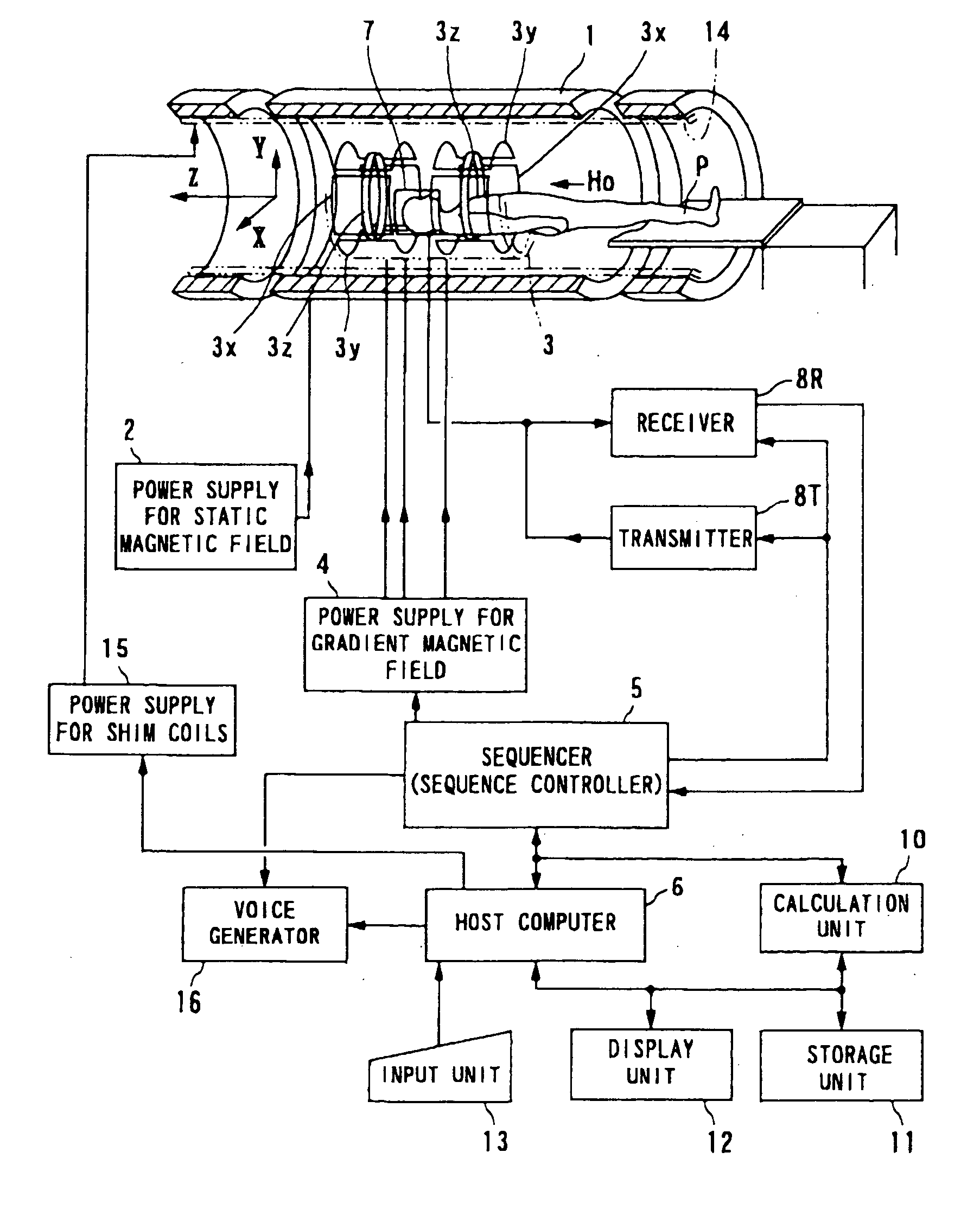
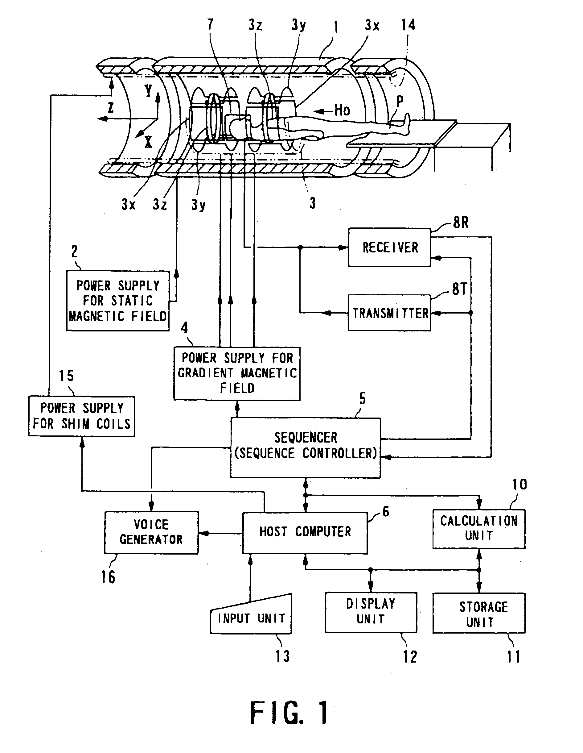
[0024]FIG. 1 schematically shows a configuration of the magnetic resonance imaging (MRI) system in the first embodiment.

[0025] The magnetic resonance imaging system comprises a table section for placing a subject P to be examined, a static magnetic field generating section for generating a static magnetic field, a gradient magnetic field generating section for adding position information to the static magnetic field, a transmitter-receiver section for transmitting and receiving a high-frequency signal, and a control-operation section for taking on control of the entire system and image reconstruction.

[0026] The static magnetic field generating section comprises, for example, a superconducting magnet 1, and a power supply 2 for static magnetic field for supplying power to the m...

second embodiment

[0062] With reference to FIGS. 5A to 5C to FIGS. 7A and 7B, a second embodiment of the magnetic resonance imaging system according to the present invention is described.

[0063] The second embodiment is characterized in that the cardiac phases are estimated by using a coil unit exclusive to a hart rate meter, and on the basis of the intensity of the MR signal acquired by the coil unit. Particularly, in the magnetic resonance imaging system related to the first embodiment described above, the actual site of imaging has been two-dimensionally scanned, as the measuring scan, using the phase contrast technique. Instead, in the present embodiment, an arrangement is so made that a coil unit exclusive to a hart rate meter is mounted on an arm (including fingertips, wrist and joints) of a subject, and the MR signal reflecting the heart rate are acquired from the arm by way of this coil unit.

[0064]FIGS. 5A to 5C illustrate an appearance of a coil unit 20 exclusive to a heart rate meter, whic...


PUM


Abstract

A magnetic resonance imaging system comprises a first RF coil for acquiring a magnetic resonance signal from a subject, and a device for estimating a cardiac phase of the subject based on the magnetic resonance signal acquired by the first RF coil. The first RF coil, for example, is an RF coil exclusive to cardiac phase estimation. The magnetic resonance imaging system further comprises a second RF coil for acquiring a magnetic resonance signal based on the estimated cardiac phase, and a device for reconstructing a magnetic resonance image of the subject based on the magnetic resonance signal acquired by the second RF coil. Thus, MRA can be performed by estimating a cardiac phase.

Description

BACKGROUND OF THE INVENTION [0001] 1. Technical Field of the Invention [0002] The present invention relates to a magnetic resonance-imaging system for medical use and a magnetic resonance signal acquisition method. More particularly, the present invention relates to a magnetic resonance imaging system which does not use an electrocardiographic (ECG) synchronizer per se, but substantially enables non-contrast MRA (MR Angiography) under ECG-gated trigger scanning and to a magnetic resonance signal acquisition method employed by the system. [0003] 2. Related Art [0004] A magnetic resonance (MR) imaging is an imaging technique for magnetically exciting nuclear spin of a subject placed in a static magnetic field by using a high-frequency signal of Larmor frequency, and for reconstructing an image by using an MR signal generated with the excitation. Such magnetic resonance imaging systems implementing this imaging method have now become essential medical modalities. [0005] In magnetic res...

Claims


Application Information

Patent Timeline
Patent Type & Authority Applications(United States)
IPC IPC(8): A61B5/05A61B5/055
CPCA61B5/055
Inventor TAKAI, HIROSHIKASSAI, YOSHIMORI
Owner TOSHIBA MEDICAL SYST CORP
Why Eureka
Try Eureka