Piezocomposite transducers

a technology of piezoceramic materials and transducers, which is applied in the direction of mechanical vibration separation, device material selection, catheters, etc., can solve the problems of significant disadvantages of materials, significant acoustic impedance mismatch, and high piezoceramic material acoustic impedance,

Inactive Publication Date: 2006-05-11
SCI MED LIFE SYST
View PDF54 Cites 138 Cited by
  • Summary
  • Abstract
  • Description
  • Claims
  • Application Information

AI Technical Summary

Benefits of technology

[0007] The embodiments described herein provide for an imaging system having an imaging device preferably insertable within a living being and configured to image the living being with a piezocomposite transducer. The piezocomposite transducer can be configured in any manner in accordance with the needs of the application. In example embodiments, the piezocomposite transducer is configured as a single element transducer, and multiple array configurations and types, including linear arrays, phased arrays, one dimensional array, two dimensional arrays, arrays having one or more rows with one or more transducers in each row, annular arrays and other arrays. Also, the piezocomposite transducer can be shaped in any manner in accordance with the needs of the application. The piezocomposite transducer preferably includes a piezoceramic material and a polymeric material. The piezoceramic material and polymeric material can be arranged in any configuration in accordance with the needs of the application. Also provided are methods of imaging with piezocomposite transducers and methods of fabricating piezocomposite transducers.

Problems solved by technology

However, these materials have significant disadvantages.
One disadvantage is that piezoceramic materials typically have an acoustic impedance much higher than the surrounding environment.
This results in a significant acoustic impedance mismatch which typically requires the use of additional matching layers around the transducer to lessen the severity of the mismatch.
However, these additional matching layers can prevent the transducer from achieving optimum performance.
Another disadvantage is that piezoceramic materials have limited ultrasound bandwidth and sensitivity.
This low coefficient severely limits the bandwidth and sensitivity of the transducer, resulting in degraded imaging performance.
Furthermore, piezoceramic materials tend to be quite fragile.

Method used


Image

  • Piezocomposite transducers
  • Piezocomposite transducers
  • Piezocomposite transducers

Examples


Embodiment Construction

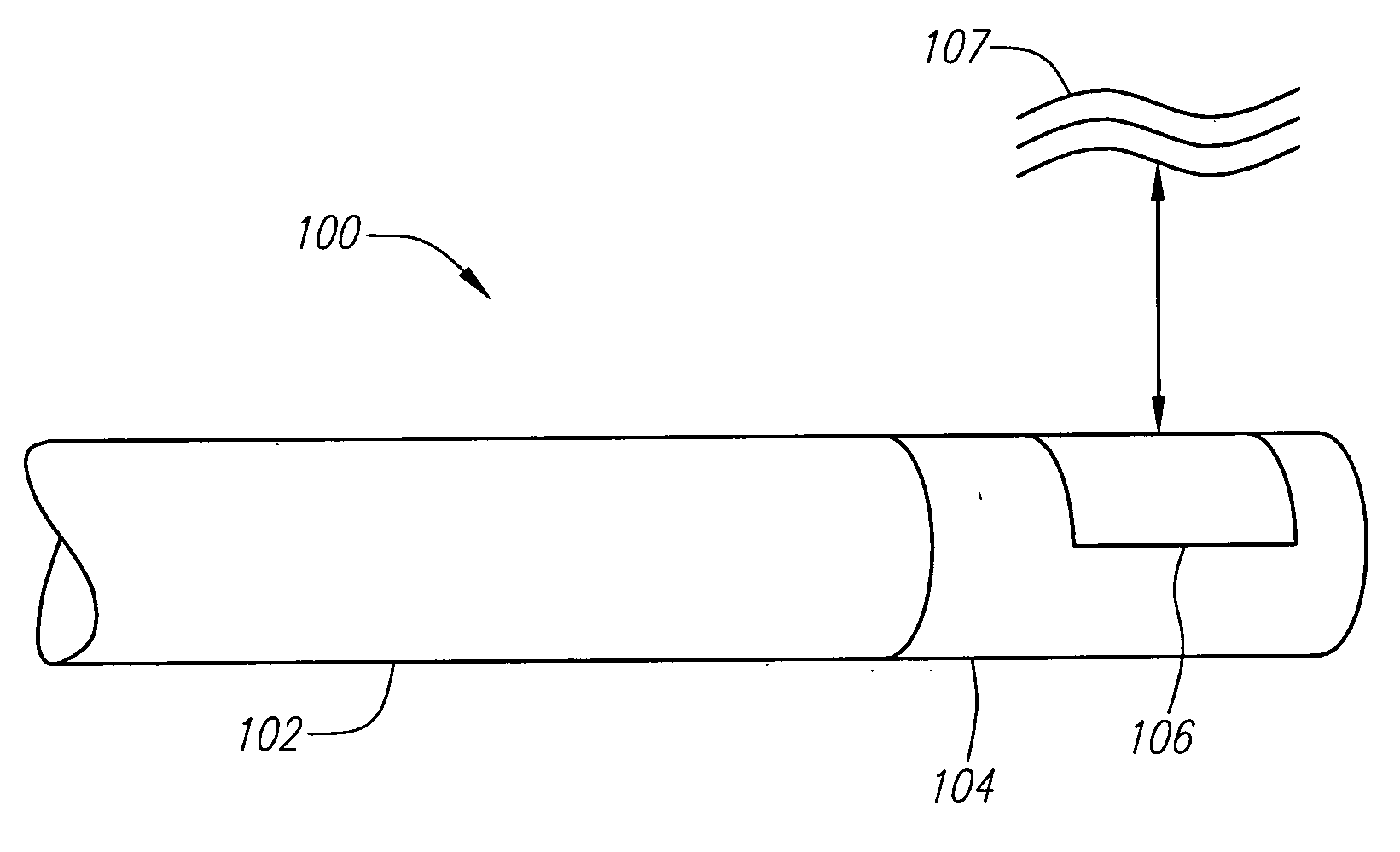
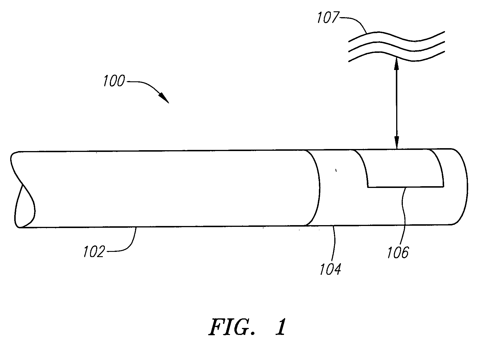
[0019] The systems and methods described herein provide for ultrasound imaging devices configured for imaging with piezocomposite materials. FIG. 1 depicts one example embodiment of an ultrasound imaging system 100 having an elongate medical device 102 configured for insertion into the body of a living being. The elongate medical device 102 includes an imaging device 104 having a piezocomposite transducer 106 for imaging tissue 107 within the interior of the living being.

[0020] The piezocomposite transducer 106 is preferably composed of a piezoceramic material and a polymer or polymeric material. The use of a piezocomposite material allows the transducer 106 to achieve improved imaging performance. For instance, piezocomposite materials have a lower acoustic impedance and higher electric-mechanical coupling coefficient, kt, than piezoceramic materials alone. Since the acoustic impedance is lower, the degree of impedance mismatch between the piezocomposite transducer 106 and the sur...


PUM


Abstract

The embodiments described herein provide for an ultrasound imaging device having a piezocomposite transducer. The imaging device is preferably insertable within a living being and configured to image the interior of the living being. The piezocomposite transducer can be formed from piezoceramic and polymeric materials. The piezocomposite transducer can be configured as a single element transducer or as a transducer array having one or more elements. Also provided is a method of manufacturing a piezocomposite transducer and a method of imaging with a piezocomposite transducer.

Description

FIELD OF THE INVENTION [0001] The systems and methods described herein relate to the fabrication, implementation and use of piezocomposite transducers in intravascular, intracardiac and similar ultrasound imaging systems. BACKGROUND INFORMATION [0002] Many diagnostic and therapeutic advantages exist in medical imaging systems that image the interior of a living being using an imaging device insertable into the living being. Examples of such systems include intravascular ultrasound (IVUS) imaging systems, intracardiac echocardiography (ICE) imaging systems and the like. These systems can be used in many applications, such as locating and treating plaque buildup within the carotoid or coronary arteries of the patient, imaging the chambers of the heart, or blood vessels and the like. Transducers used within these imaging devices are typically formed from strictly piezoceramic materials. However, these materials have significant disadvantages. [0003] One disadvantage is that piezocerami...

Claims


Application Information

Patent Timeline
Patent Type & Authority Applications(United States)
IPC IPC(8): A61B8/14
CPCA61B8/12A61B8/4483A61B8/445H01L41/18B06B1/0622H10N30/852
Inventor YUAN, JIAN R.CAO, PEI JEIROMLEY, RICHARD
Owner SCI MED LIFE SYST
Why Eureka
Try Eureka