Inflatable device for use in surgical protocol relating to fixation of bone

a technology of inflatable devices and bone fixation, which is applied in the direction of osteosynthesis devices, prostheses, catheters, etc., can solve the problems of limited parting lines, no disclosures relating to inflatable devices used in bone, and no disclosures relating to bone compacting devices in vertebral bodies and long bones, etc., to improve the clinical outcome and worsen the condition

Inactive Publication Date: 2006-05-11
ORTHOPHOENIX
View PDF17 Cites 140 Cited by
  • Summary
  • Abstract
  • Description
  • Claims
  • Application Information

AI Technical Summary

Benefits of technology

[0024] In particular, the present invention is directed to a balloon for use in treating a bone predisposed to fracture or to collapse. The balloon comprises an inflatable, non-expandable balloon body for insertion into said bone. The body has a predetermined shape and size when substantially inflated sufficient to compress at least a portion of the inner cancellous bone to create a cavity in the cancellous bone and to restore the original position of the outer cortical bone, if fractured or collapsed. The balloon body is restrained to create said predetermined shape and size so that the fully inflated balloon body is prevented from applying substantial pressure to the inner surface of the outer cortical bone if said bone is unfractured or uncollapsed.
[0056] The hemispherical balloon approximates the shape of the top half of the femoral (and humeral) head, and provides a means for compacting cancellous bone in an area of avascular necrosis or small fracture without disturbing the rest of the head. This makes it easier to do a future total joint replacement if required.

Problems solved by technology

While the apparatus and method of the above patents provide an adequate protocol for the fixation of bone, it has been found that the compacting of the bone marrow and / or the trabecular bone and / or cancellous bone against the inner surface of the cortical wall of the bone to be treated can be significantly improved with the use of inflatable devices that incorporate additional engineering features not heretofore described and not properly controlled with prior inflatable devices in such patents.
However, there is a scarcity of disclosures relating to inflatable devices used in bone, and none for compacting bone marrow in vertebral bodies and long bones.
However, this technique of extrusion forms parting lines in the balloon product which parting lines are limiting in the sense of providing a weak wall for the balloon itself.
It does not teach the shape of the balloon which creates a cavity that best supports the bone when appropriately filled.
It does not teach how to prevent balloons from being spherical when inflated, when this is desired.
Current medical balloons can compress bone but are too small and generally have the wrong configuration and are generally not strong enough to accomplish adequate cavity formation in either the vertebral bodies or long bones of the body.

Method used


Image

  • Inflatable device for use in surgical protocol relating to fixation of bone
  • Inflatable device for use in surgical protocol relating to fixation of bone
  • Inflatable device for use in surgical protocol relating to fixation of bone

Examples


first embodiment

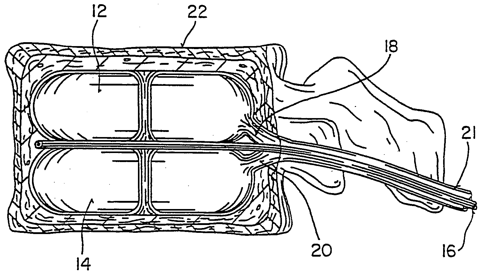
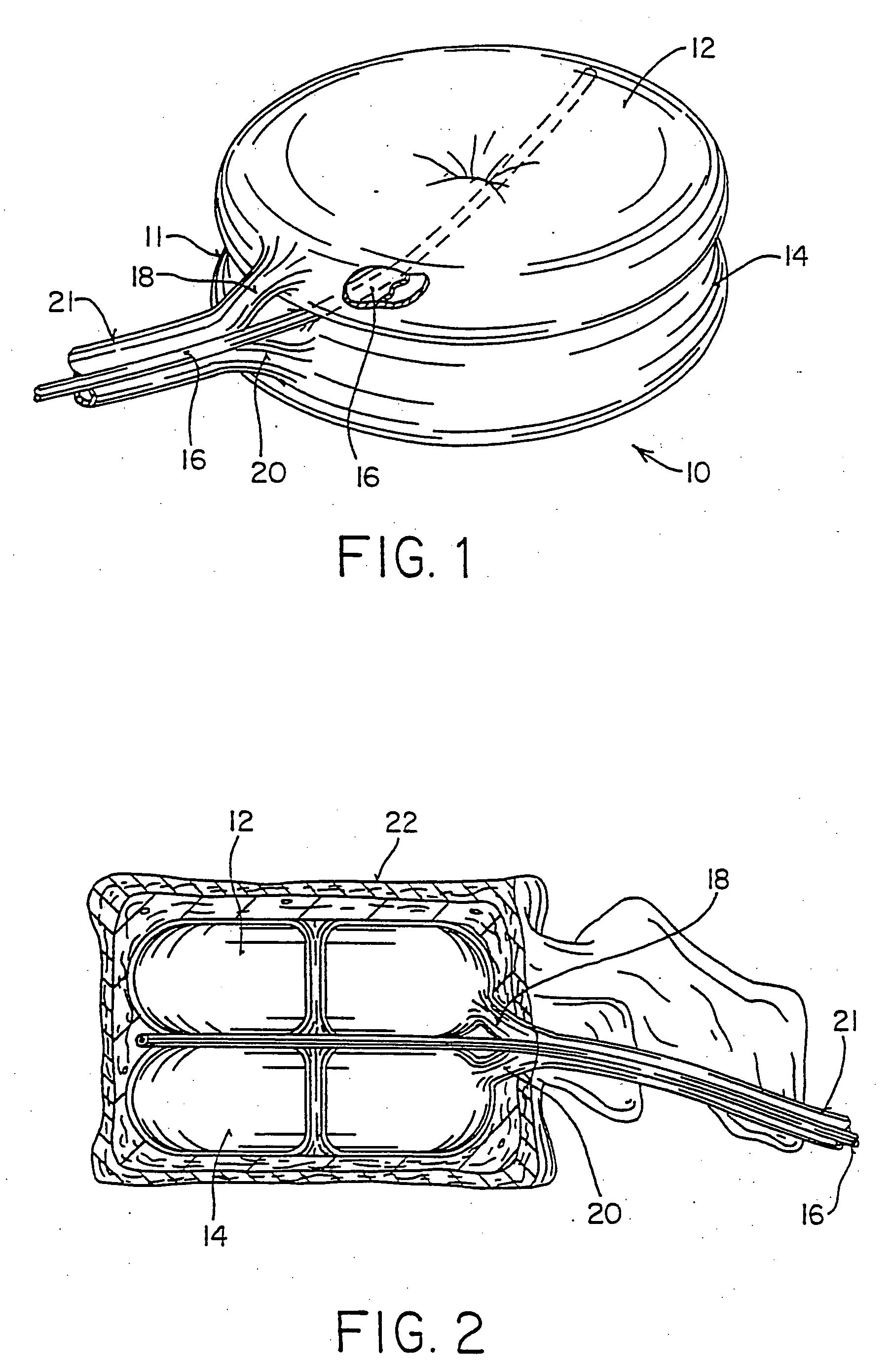
[0094] the balloon (FIG. 1) of the present invention is broadly denoted by the numeral 10 and includes a balloon body 11 having a pair of hollow, inflatable, non-expandable parts 12 and 14 of flexible material, such as PET or Kevlar. Parts 12 and 14 have a suction tube 16 therebetween for drawing fats and other debris by suction into tube 16 for transfer to a remote disposal location. Catheter 16 has one or more suction holes so that suction may be applied to the open end of tube 16 from a suction source (not shown).

[0095] The parts 12 and 14 are connected together by an adhesive which can be of any suitable type. Parts 12 and 14 are doughnut-shaped as shown in FIG. 1 and have tubes 18 and 20 which communicate with and extend away from the parts 12 and 14, respectively, to a source of inflating liquid under pressure (not shown). The liquid can be any sterile biocompatible solution. The liquid inflates the balloon 10, particularly parts 12 and 14 thereof after the balloon has been in...

second embodiment

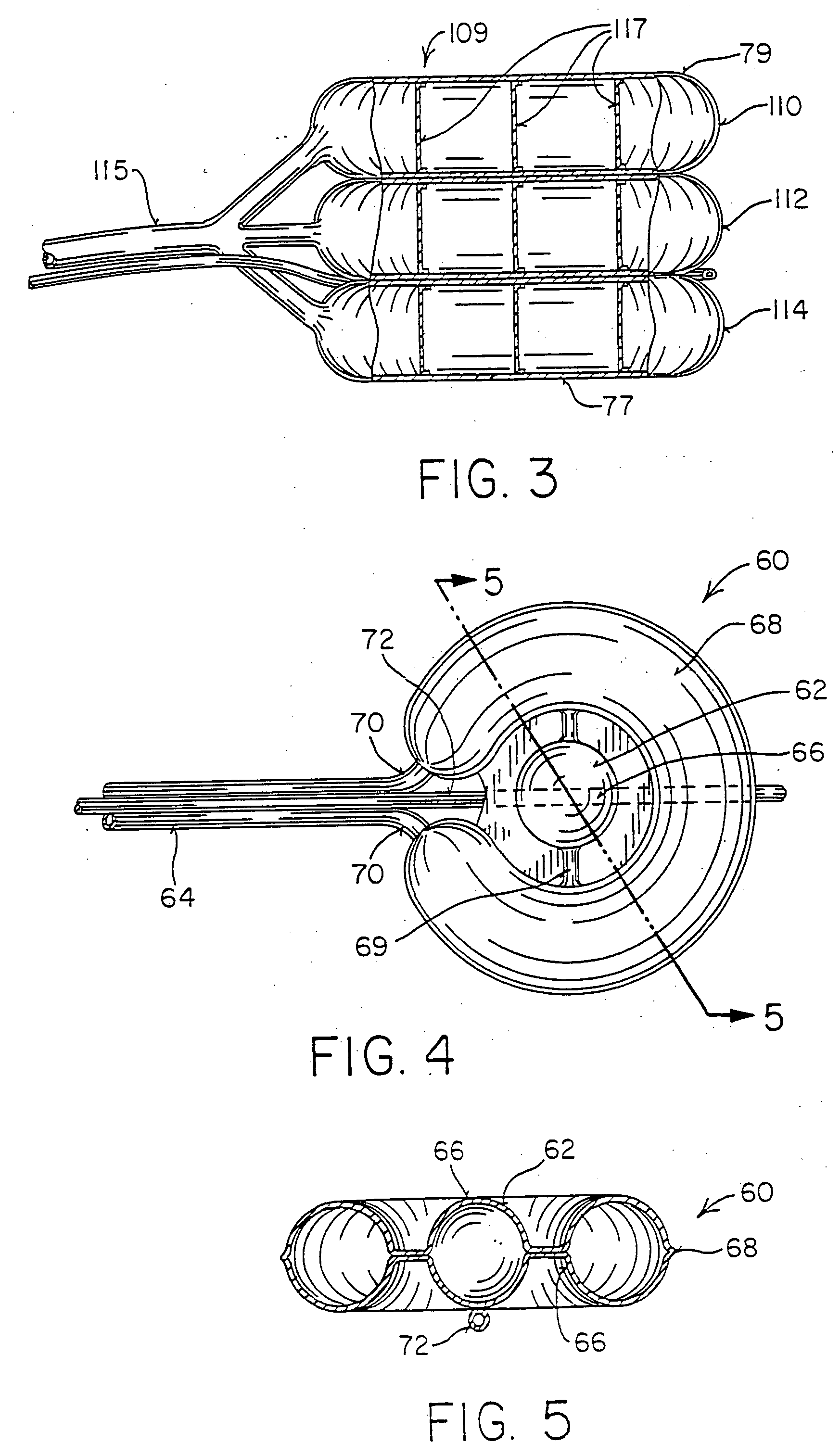
[0099] the inflatable device of the present invention is broadly denoted by the numeral 60 and is shown in FIGS. 4 and 5. Balloon 60 includes a central spherical part 62 which is hollow and which receives an inflating liquid under pressure through a tube 64. The spherical part is provided with a spherical outer surface 66 and has an outer periphery which is surrounded substantially by a ring shaped part 68 having tube segments 70 for inflation of part 68. A pair of passages 69 interconnect parts 62 and 68. A suction tube segment 72 draws liquid and debris from the bone cavity being formed by the balloon 60.

[0100] Provision can be made for a balloon sleeve 71 for balloon 60 and for all balloons disclosed herein. A balloon sleeve 71 (FIG. 9) is shiftably mounted in an outer tube 71a and can be used to insert the balloon 60 when deflated into a cortical bone. The sleeve 71 has resilient fingers 71b which bear against the interior of the entrance opening 71c of the vertebral bone 22 (FI...


PUM

PropertyMeasurementUnit
pressuresaaaaaaaaaa
pressuresaaaaaaaaaa
heightaaaaaaaaaa

Abstract

Systems for treating a bone, e.g. a vertebral body, having an interior volume occupied, at least in part, by cancellous bone provide a first tool, a second tool, and a third tool. The first tool establishes a percutaneous access path to bone. The second tool is sized and configured to be introduced through the percutaneous access path to form a void that occupies less than the interior volume. The third tool places within the void through the percutaneous access path a volume of filling material. Related methods for treating a bone, e.g. a vertebral body, having an interior volume occupied, at least in part, by cancellous bone provide establishing a percutaneous access path to bone. A tool is introduced through the percutaneous access path and manipulated to form a void that occupies less than the interior volume. A volume of filling material is then placed within the void through the percutaneous access path.

Description

RELATED APPLICATIONS [0001] This application is a divisional of co-pending application Ser. No. 10 / 747,547, filed 29 Dec. 2003 which is a divisional of Ser. No. 10 / 411,573, filed Apr. 10, 2003, which is a divisional of application Ser. No. 10 / 200,674, filed Jul. 22, 2002, which is a divisional of Ser. No. 09 / 059,796, filed Apr. 13, 1998, now U.S. Pat. No. 6,423,083, which is a divisional of application Ser. No. 08 / 788,786, filed Jan. 23, 1997, now U.S. Pat. No. 6,235,043, which is a continuation of application Ser. No. 08 / 188,224, filed on Jan. 26, 1994 (now abandoned).FIELD OF THE INVENTION [0002] This invention relates to improvements in the surgical treatment of bone conditions of the human and other animal bone systems and, more particularly, to an inflatable balloon-like device for use in treating such bone conditions. Osteoporosis, avascular necrosis and bone cancer are diseases of bone that predispose the bone to fracture or collapse. There are 2 million fractures each year i...

Claims


Application Information

Patent Timeline
Patent Type & Authority Applications(United States)
IPC IPC(8): A61B17/58A61B17/02A61B17/68A61B17/88A61F2/00A61F2/28A61F2/44A61F2/46A61F2/958A61M29/00
CPCA61B17/8855A61B2017/0256A61F2/28A61F2/441A61F2/4601A61F2/4611A61F2002/30535A61F2250/0058A61M25/10A61M25/1002A61M29/02A61M2210/02A61M2210/1003
Inventor REILEY, MARK A.SCHOLTEN, ARIETAIMADGE, KAREN
Owner ORTHOPHOENIX
Why Eureka
Try Eureka