
System, method and apparatus for an extensible distributed enterprise integration platform

Inactive Publication Date: 2006-05-11
INTEGRATION TECH
View PDF10 Cites 66 Cited by
  • Summary
  • Abstract
  • Description
  • Claims
  • Application Information

AI Technical Summary

Benefits of technology

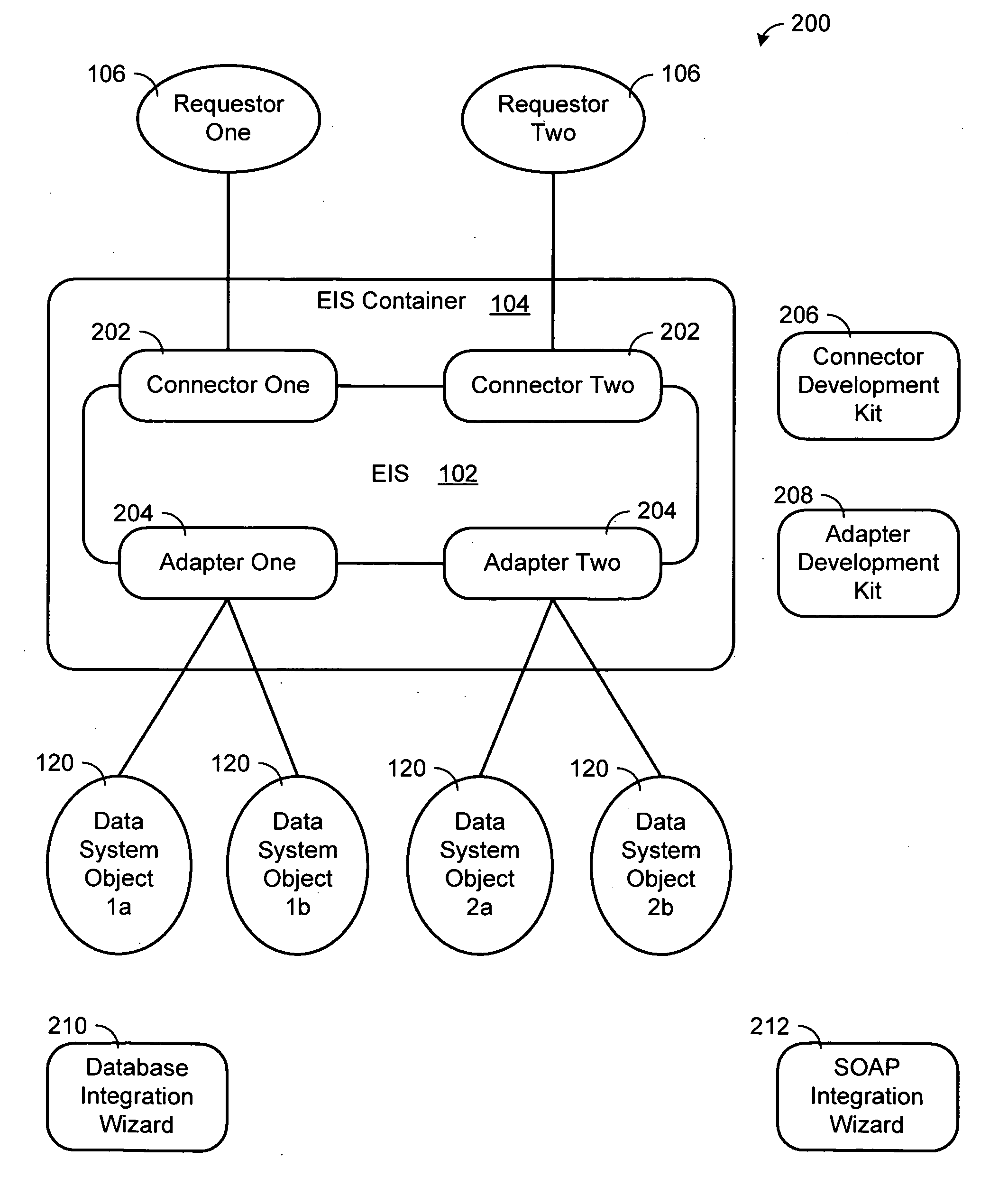
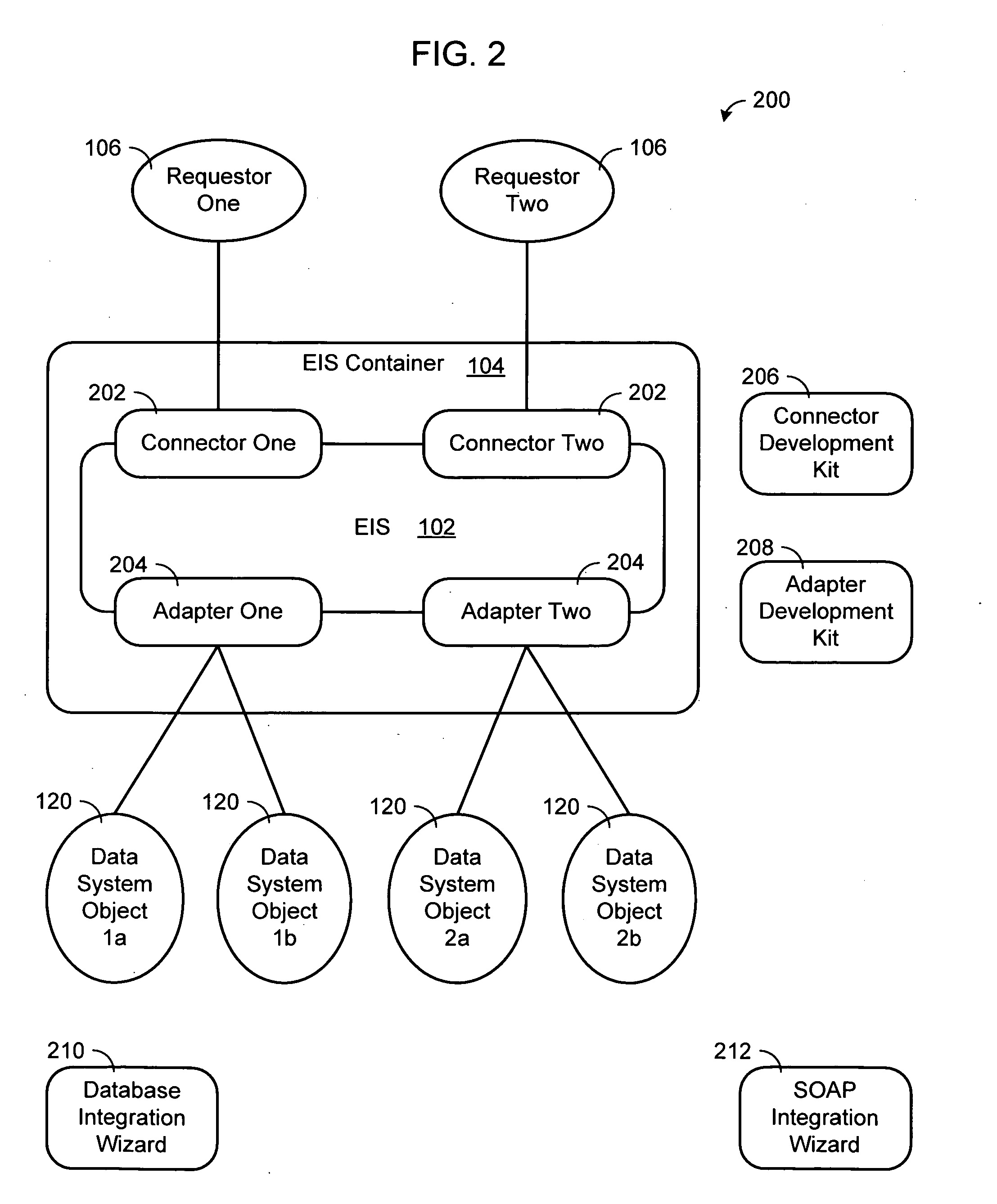
[0010] The platform can extend to accommodate new systems by writing new connectors and adapters that implement application program interfaces (APIs), which translate systems protocols to a common format understood by the platform. This decoupling of the transformation server from the external system protocol has the effect of simplifying the server and allowing it to appear as different types of servers depending on which API is used to connect to it. For example, when using the HTML API the server appears to be a Web Server, when using the SOAP API the server appears to be a SOAP Server, when using the WAP API the server appears to be a WAP Server, when using the AMF API the server appears to be a Flash Remoting Server, etc.
[0011] The dynamic generation of system queries and commands based on the incoming data translated into internal format allows building flexible and generic integration transactions applicable to the variety of data sources and destinations without necessity to develop a new code. Furthermore, the combination of systems integration via a server, involving no definition or generation of program code, the decoupling of protocols, the dynamic command generation, the ability to easily accommodate new data systems and technologies, and the ability to masquerade as other servers, is to our knowledge is unique in the industry. As a result, the present invention provides for significant time and cost advantages over other approaches of systems integration.

Problems solved by technology

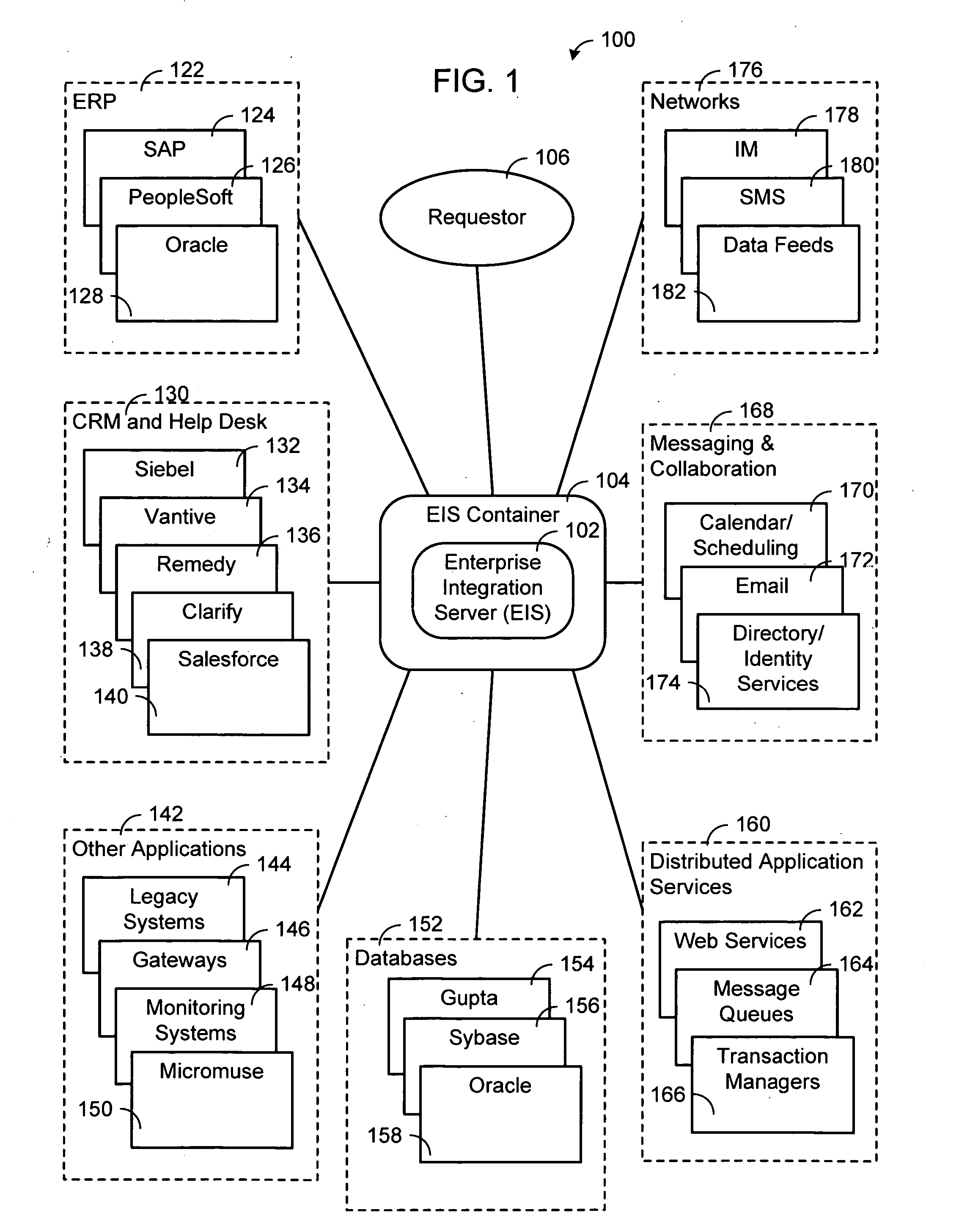
Because these systems where developed at different points in time, by different project teams, using different technology, these systems typically are not fully compatible and have limited ability to interoperate,
The problem with these solutions is that they are time-consuming and costly to develop and support due to their technical complexity and limited commonality and re-usability of solutions for one instance of the problem to the next.

Method used


Image

  • System, method and apparatus for an extensible distributed enterprise integration platform
  • System, method and apparatus for an extensible distributed enterprise integration platform
  • System, method and apparatus for an extensible distributed enterprise integration platform

Examples


Embodiment Construction

[0023] While the making and using of various embodiments of the present invention are discussed in detail below, it should be appreciated that the present invention provides many applicable inventive concepts that can be embodied in a wide variety of specific contexts. The specific embodiments discussed herein are merely illustrative of specific ways to make and use the invention and do not delimit the scope of the invention. The discussion herein relates primarily to enterprise integration systems, but it will be understood that the concepts of the present invention are applicable to any transaction processing system in which automatic integration is desireable.

[0024] The present invention provides a system, method and apparatus for an extensible distributed enterprise integration platform that solves the problems associated with current software integration programs and focuses on embedding the systems integration process in to a platform which companies can use to integrate syst...


PUM


Abstract

The present invention provides a system, method and apparatus for an extensible distributed enterprise integration platform that includes a server communicably coupled to a connector and an adapter. The server loads a transaction from a translated service request, executes each transaction step of the transaction by identifying an adapter to communicate with a resource, determining a result for the executed transaction step, creating a service response for the service request and passing the service response to the connector. The connector receives the service request from a requestor, translates the service request, passes the translated service request to the server, translates the service response and sends the translated service response to the requester. The adapter establishes a session with the resource, translates the transaction step, sends the request to the resource, receives a response from the resource, translates the response and passes the translated response to the server.

Description

REFERENCE TO RELATED APPLICATIONS [0001] This application claims priority to U.S. Provisional Patent Application No. 60 / 626,164 filed Nov. 8, 2004 entitled Extensible Distributed Enterprise Integration Platform, which is herein incorporated by reference in its entirety.FIELD OF THE INVENTION [0002] The present invention relates generally to the field of transaction processing systems (e.g., “Information Integration Management”, “Enterprise Application Integration” and “Enterprise Information Integration”) and, more particularly, to a connector-server-adapter architecture used to act upon and integrate applications and data normally deployed in networked computing environments. BACKGROUND OF THE INVENTION [0003] Over the last several decades, organizations have spent hundreds of billion of dollars creating and maintain applications and databases (heretofore referred to as “systems”) that support their business. Because these systems where developed at different points in time, by dif...

Claims


Application Information

Patent Timeline
IPC IPC(8): G06F9/44
CPCG06F9/5027G06F9/541G06F2209/5016
Inventor MAGOWN, BRUCE
Owner INTEGRATION TECH
Learn More