Lamp

a technology for led chips and back wall, applied in the field of lamps, can solve the problems of difficult to directly fix the led chip to the inner face of the back wall, etc., and achieve the effects of convenient handling, convenient operation, and convenient mounting

Inactive Publication Date: 2006-05-18
TOYODA GOSEI CO LTD
View PDF4 Cites 22 Cited by
  • Summary
  • Abstract
  • Description
  • Claims
  • Application Information

AI Technical Summary

Benefits of technology

[0016] A manner of providing the lead to the reflection case is not limited to a specific manner, however, it is preferable to use a lead inserted in the injection molding process of the reflection case. Furthermore, it is preferable that the lead is exposed to at least the central portion in the width direction of the back wall inner face, and the back side of the sub mount table is fixed to the lead. This fixing method is not limited to a specific one, however, it is preferable to use the excellent heat transfer material which is easily handle...

Problems solved by technology

However, since an LED chip which is generally used as the light emitting element 110 is very small, it is di...

Method used


Image

  • Lamp
  • Lamp
  • Lamp

Examples


examples

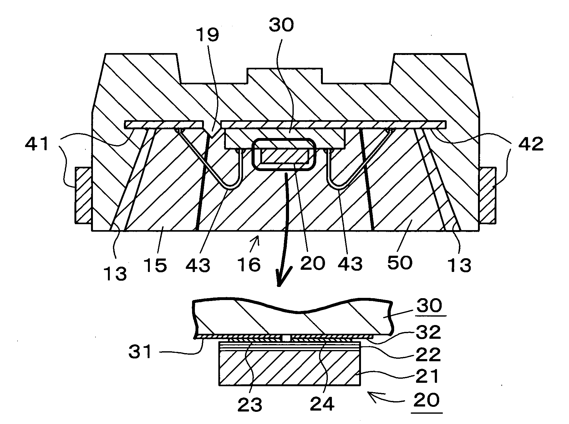
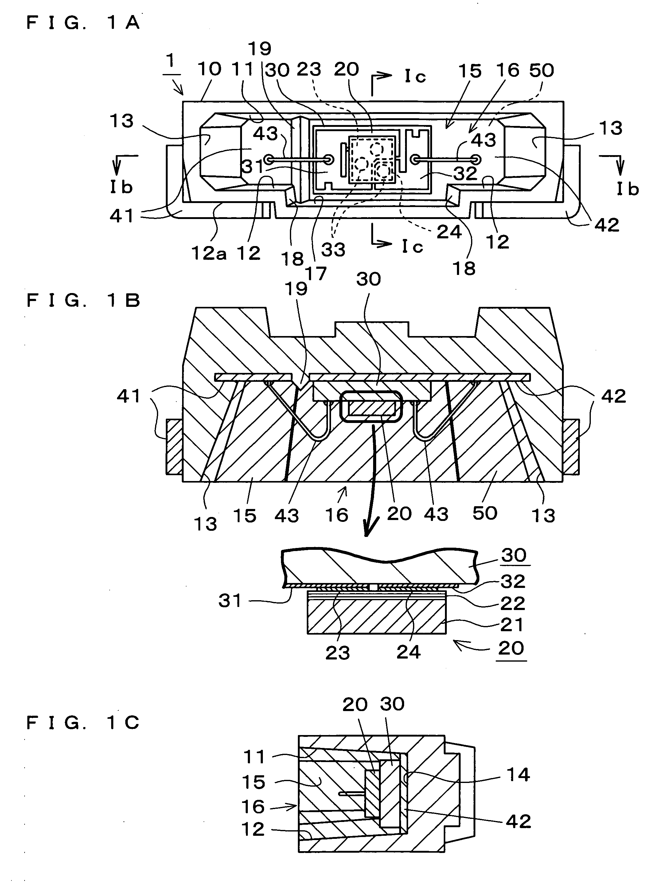
[0024] The lamp 1 of the embodiment shown in FIGS. 1 and 2 comprises a white color lamp in which the light emitting element 20 is mounted on the sub mount table 30, the sub mount table 30 is fixed to the reflection case 10, and the electrodes of the light emitting element 20 are connected to the leads 41, 42 provided to the reflection case 10.

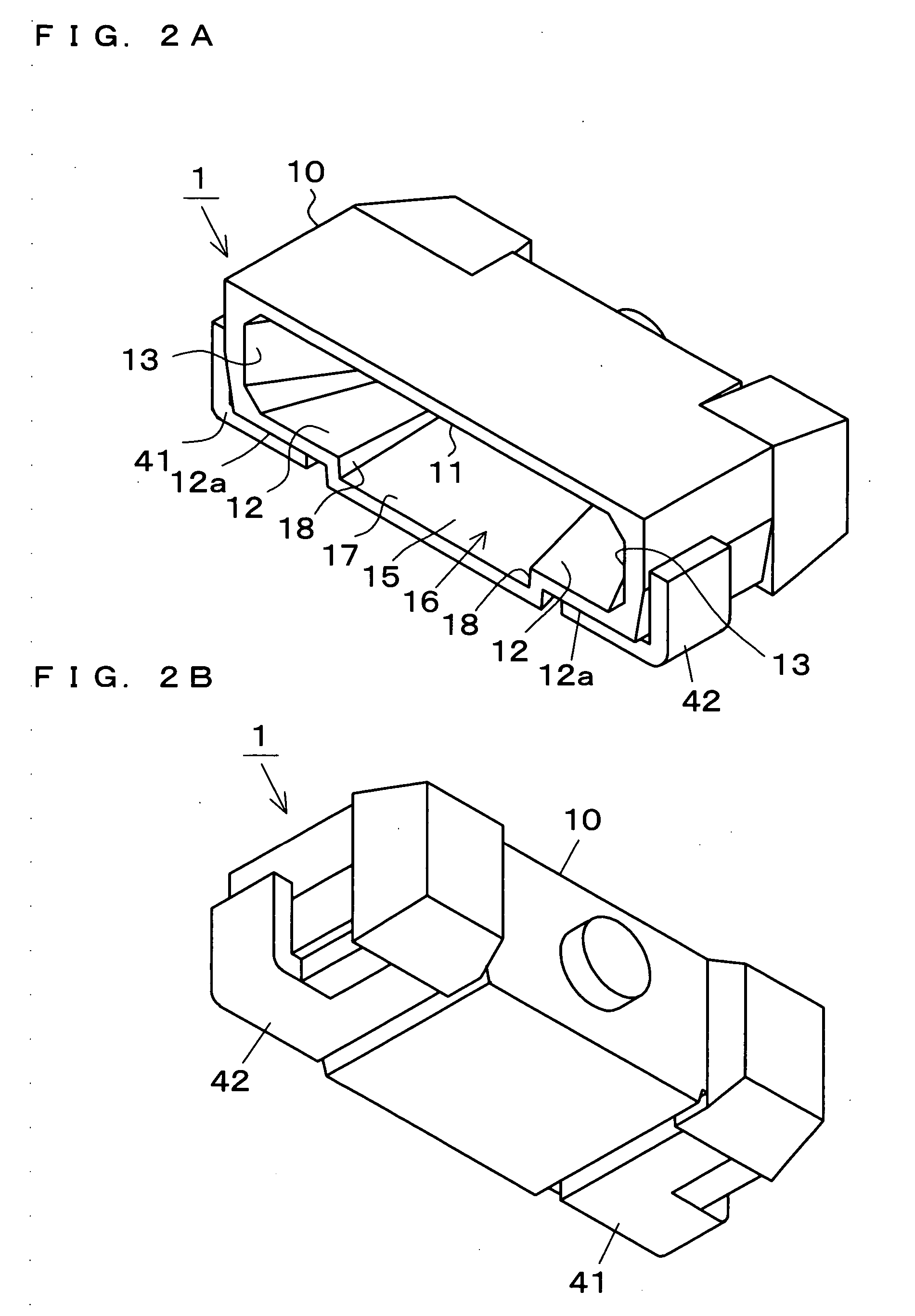
[0025] The reflection case 10 is formed of nylon resin by injection molding, and it is provided with an upper wall inner face 11, a lower wall inner face 12 and a lower wall enlarged inner face 17 which are disposed so as to confront each other at a relatively small interval, right and left side wall inner faces 13 which are disposed so as to confront each other at a relatively large interval, a back wall inner face 14, a recess portion 15 surrounded by the above inner faces, and a front opening 16.

[0026] The central portion in the width direction of the lower wall inner face 12 is stepwise lowered to form the lower wall enlarged inner face 1...


PUM


Abstract

The present invention provides a lamp that includes a reflection case and a light emitting element. A central portion of a lower wall inner face of the reflection case is stepwise lowered to form a lower wall enlarged inner face, and both faces are made continuous with each other through right and left perpendicular hanging inner faces, so that a central portion of a back wall inner face and a front opening are downwardly enlarged in a rectangular shape, respectively. The light emitting element is mounted on a front face of a sub mount table. A back face of the sub mount table is fixed to the central portion of the back wall inner face, and right and left end faces of the sub mount table are positioned to right and left perpendicular hanging inner faces when the sub mount table is fixed.

Description

BACKGROUND OF THE INVENTION [0001] 1. Field of the Invention [0002] The present invention relates to a lamp constructed by providing an LED (light emitting diode) chip to a reflection case having an opening at the front side thereof. [0003] 2. Description of the Related Art [0004] A plane light emitting device for making light from a light source incident to an end face of a light guide plate and emitting light in the form of a plane from the light emitting face of the light guide plate is used for liquid crystal back light, a panel meter, a display lamp, a plane light emitting switch or the like. With respect to lamps used as one type of light sources, it is required to design the lamps as a thin type in connection with the thickness of the light guide plate, and thus it is general to use a lamp constructed by providing a light emitting element to a thin reflection case having a front opening. For example, Japanese laid-open patent publication number Hei 8-264842 describes a lamp s...

Claims


Application Information

Patent Timeline
IPC IPC(8): E04B1/74H01L33/60H01L33/62
CPCH01L33/60H01L2224/48091H01L2224/48247Y10S362/80H01L2224/73265H01L2224/49107H01L2924/00014
Inventor TSUZUKI, ATSUSHITAKAHASHI, YUJIHAYASHI, TOSHIMASAARAKANE, KATSUNORI
Owner TOYODA GOSEI CO LTD
Why Eureka
Try Eureka