Safety harnesses

a full body, safety technology, applied in the direction of safety belts, constructions, building aids, etc., can solve the problems of significant pulling (that is, tension in the strapping) on the lower torso or seat portion of the harness, and achieve the effect of less tension

Inactive Publication Date: 2006-05-18
HONEYWELL INT INC
View PDF59 Cites 62 Cited by
  • Summary
  • Abstract
  • Description
  • Claims
  • Application Information

AI Technical Summary

Benefits of technology

[0021] In one aspect, the present invention provides a full body safety harness to be worn by a person including an upper torso portion and a lower seat portion. The upper torso portion is operatively connected to the lower seat portion by a first connector on a first lateral side and a second connector on a second lateral side thereof. The first connector and the second connector enable forward and rearward rotation of the upper torso portion relative to the lower seat portion (as in the case of forward and rearward bending by a user of the harness) without causing a significant increase in tension in the lower seat portion. The less tension increases in the lower torso portion during bending, the better. Such tension increases in the lower torso portion of the harnesses of the present invention upon bending can, for example, be reduced to less than 10% or even substantially eliminated.

Problems solved by technology

Although the comfort of safety harnesses during normal use and even during a fall arrest has been greatly improved in the above-described harnesses, the underlying design of currently available safety harnesses still leads to a number of problems including, for example, range of motion problems, comfort problems, donning problems, adjustment problems and webbing wear problems. FIG. 1 illustrates an embodiment of a conventional, commercially available full-body safety harness 10 Safety harness 10 includes an upper torso portion 12 comprising first and second shoulder straps 20 and 30, respectively, for extending over the shoulders of the user and a multi-component chest strap 40 for extending over a portion of the chest of the user.
In general, it is difficult, for example, to bend forward or rearward in a harness such as harness 10 and other harnesses because of the resistance of the interconnected strapping material forming the harness.
In that regard, bending forward and / or rearward causes significant pulling (that is, tension in the strapping) on the lower torso or seat portion of the harness.
A number of problems exist with current back pad designs.
Moreover, current back pad designs provide little if any protection to the safety harness or the user of the safety harness from, for example, impact from sharp and / or heavy equipment such as snap hooks and / or self-retracting lifelines which are typically connected to rear D-rings positioned at the crossing point of the shoulder straps.
Such impacts can damage the straps of the safety harness and injure the wearer.
Further, current back pads do not adequately provide for the comfort of the user.
In addition to the above-identified problems, users of currently available safety harnesses find it very difficult to adjust the fit of the safety harness and other fall protection safety gear using friction buckles and other types of adjustment mechanisms found on such safety harnesses.
Moreover, this difficulty can often be increased with the use of harness webbing material designed to increase the comfort of the user.
Furthermore, it is often difficult to don currently available safety harnesses.
Although efforts have been made to simplify the donning of a safety harness by, for example, fabricating the harness material so that the harness maintains its form when not worn as described in U.S. Pat. No. 6,739,427 or by providing a back connector assembly sufficiently rigid to give an undonned harness some shape (see, for example, U.S. Pat. No. 6,253,874), problems in donning persist.
For example, it is often difficult of the user of the harness to determine which side of the harness material is the outer or inner side, leading to donning of the harness in and inside-out conformation.
Moreover, webbing material used in currently available safety harnesses and other fall protection safety gear is susceptible to fraying, particularly at the end thereof.

Method used


Image

  • Safety harnesses
  • Safety harnesses
  • Safety harnesses

Examples


Embodiment Construction

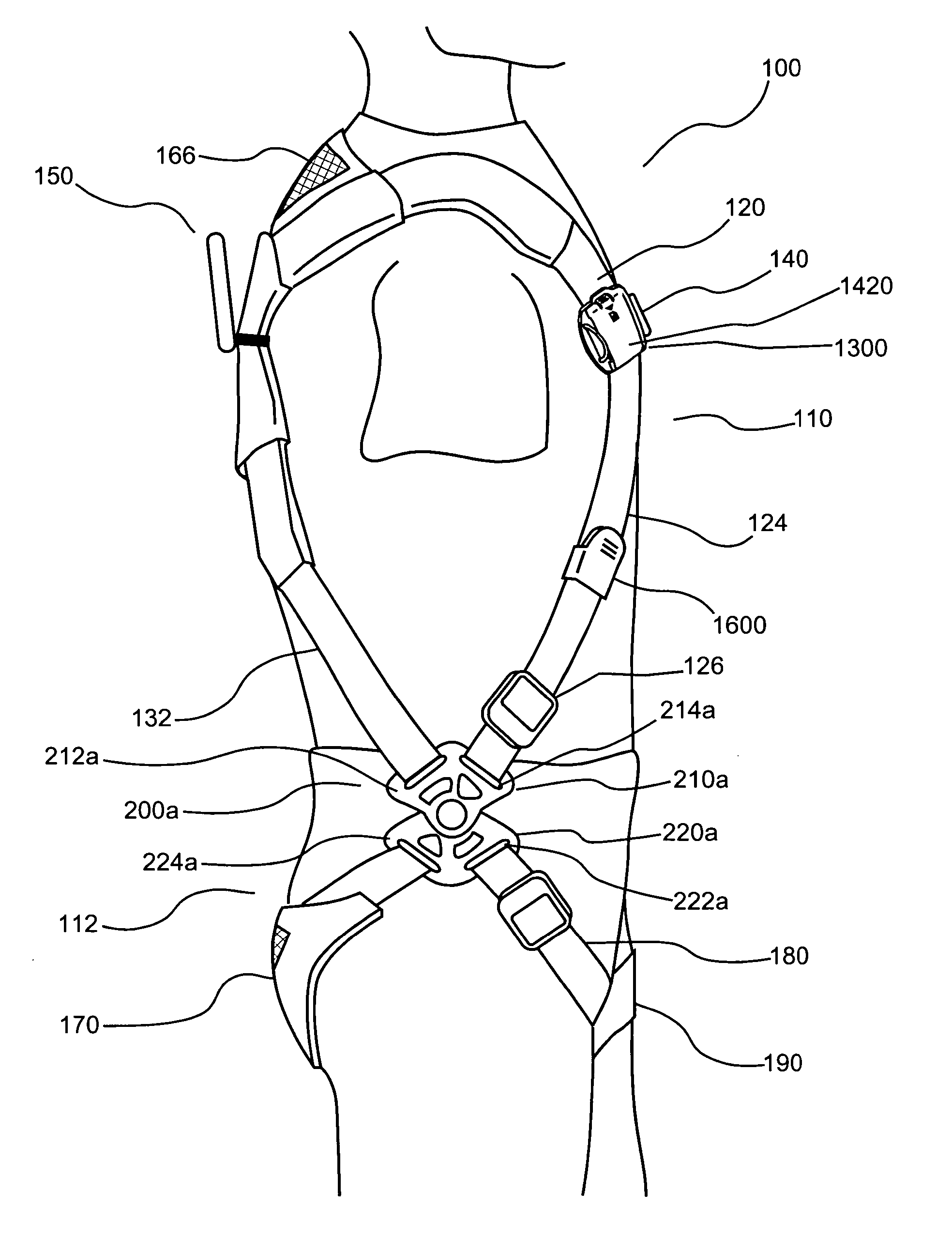
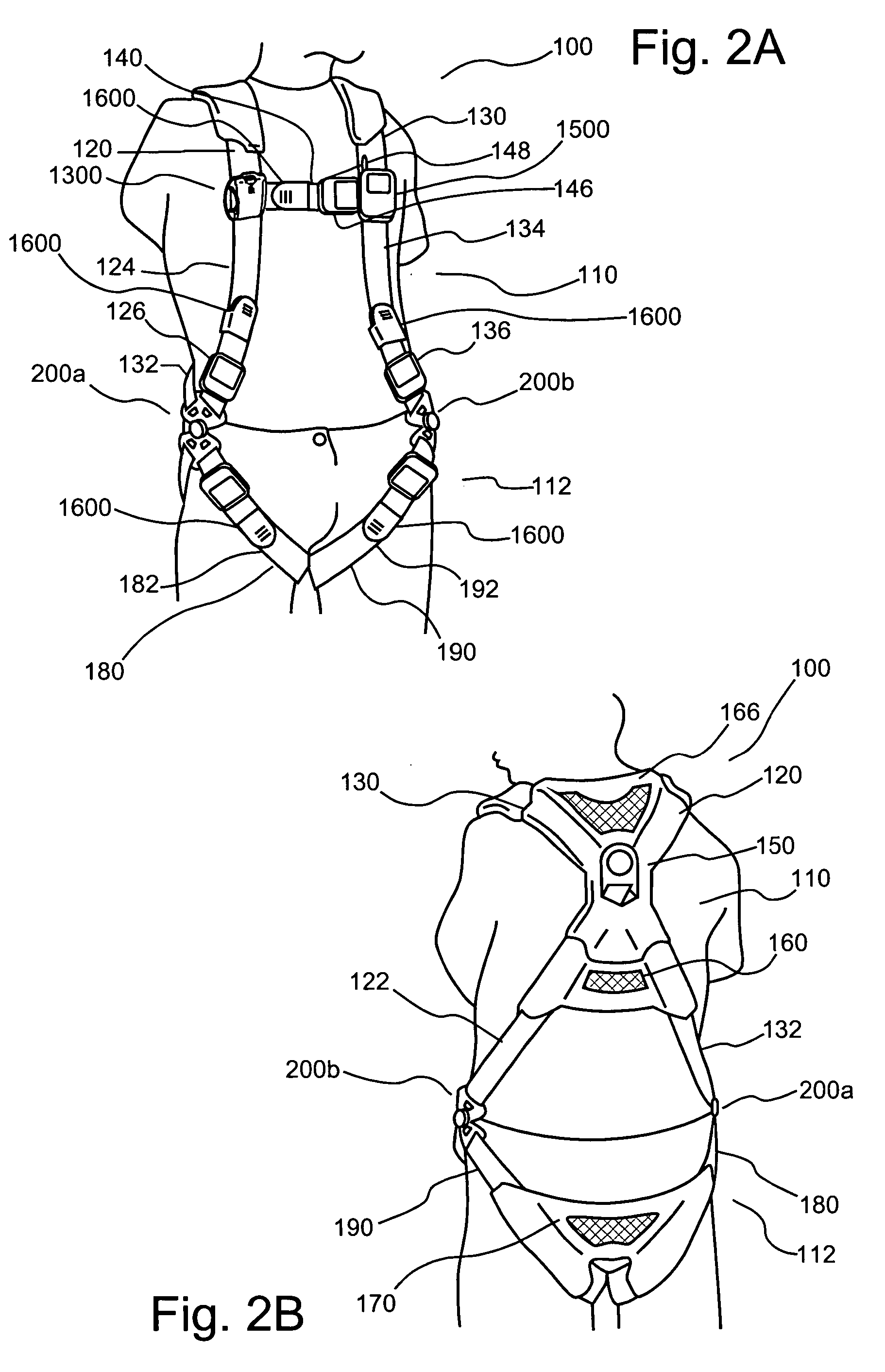
[0144]FIGS. 2A through 2G illustrate one embodiment of a full body safety harness 100 of the present invention. Safety harness 100 includes an upper torso section, portion or module 110 and a lower torso (seat) section, portion or module 112. Upper torso portion 110 includes a first shoulder strap 120 and a second shoulder strap 130 extending over the shoulders of the user and a multi-component chest strap 140 extending between first shoulder strap 120 and second shoulder strap 130. First ends of each of shoulder straps 120 and 130 extend down over the back of the user to form first and second generally longitudinal back straps 122 and 132, respectively. Back straps 122 and 132 cross through and connect to a D-ring 150 in a manner similar to that described above in connection with D-ring 50. After crossing and passing through D-ring 150, back strap sections 122 and 132 of shoulder straps 120 and 130 are connected via a generally latitudinal back strap 160, which passes generally lat...


PUM


Abstract

A back pad for use in connection with a safety harness including at least two spaced back straps. The back pad includes a shield covering at least a portion of each of the back straps of the safety harness. The shield extends between the back straps to cover a portion of a user's back when the safety harness is worn. A full body safety harness to be worn by a person includes an upper torso portion and a lower seat portion. The upper torso portion is operatively connected to the lower seat portion by a first connector on a first lateral side and a second connector on a second lateral side thereof. The first connector and the second connector can, for example, enable forward and rearward rotation of the upper torso portion relative to the lower seat portion (for example, without causing a significant increase in tension in the upper torso portion or the lower seat portion). At least one of the first connector and the second connector includes a shaft. The upper torso portion includes at least one connecting member having a passage formed therein. The lower seat portion includes at least one connecting member have a passage formed therein. The shaft passes through the passage of the at least one connecting member of the upper torso portion and through the passage of the at least one connecting member of the lower torso portion.

Description

CROSS-REFERENCE TO RELATED APPLICATIONS [0001] The present invention is a continuation in part application of U.S. patent application Ser. No. 11 / 179,228, filed Jul. 12, 2005, which claims benefit of U.S. Provisional Patent Application Ser. No. 60 / 587,130, filed Jul. 12, 2004, and U.S. Provisional Patent Application Ser. No. 60 / 611,438, filed Sep. 20, 2004, the disclosures of which are incorporated herein by reference.BACKGROUND OF THE INVENTION [0002] The present invention relates generally to full body safety harnesses, and particularly to safety harnesses which, for example, provide improved or enhanced range of motion, comfort, ease of donning, ease of adjustment and ease of adding accessory equipment as compared to other safety harnesses. [0003] References set forth herein may facilitate understanding of the present invention or the background of the present invention. Inclusion of a reference herein, however, is not intended to and does not constitute an admission that the ref...

Claims


Application Information

Patent Timeline
Patent Type & Authority Applications(United States)
IPC IPC(8): E04G3/28
CPCA62B35/0012A62B35/0018A62B35/0025A62B35/04
Inventor LANG, TRACY H.FREY, JOHN R.ANDERSON, PRESTON L.
Owner HONEYWELL INT INC
Why Eureka
Try Eureka