Wire electric discharge machine and wire electric discharge machining method

a wire electric discharge and wire electric discharge technology, which is applied in the direction of electrical-based machining electrodes, welding apparatus, manufacturing tools, etc., can solve the problems of taper machining, possible measurement of workpiece set posture error, and possible measurement of machined surface angle error (a) or machined shape distortion error, etc., to achieve the effect of improving the machining accuracy and improving the operation efficiency of the wire electric discharge machining

Inactive Publication Date: 2006-05-18
FANUC LTD
View PDF2 Cites 39 Cited by
  • Summary
  • Abstract
  • Description
  • Claims
  • Application Information

AI Technical Summary

Benefits of technology

[0011] The object of the present invention is to provide a wire electric discharge machine and a wire electric discharge machining method capable of appropriately coping with the aforementioned error problem, thereby improving the machining accuracy.
[0017] If the workpiece is not set horizontally with respect to the XY-plane, wire electric discharge machining can be executed with the error (a) or the errors (a) and (b) compensated for by utilizing the result of inclination detection. In consequence, the operating efficiency of the wire electric discharge machining and the machining accuracy can be improved with ease.

Problems solved by technology

This error causes the aforesaid machined surface angle error (a) or machined shape distortion error (b).
However, the electrode 7 fails to be perpendicular to the upper surface 31 of the workpiece 30, so that taper machining is inevitably executed with the machined surface inclined at an angle corresponding to the workpiece set posture error.
The workpiece set posture error may possibly be measured after wire connection.
As mentioned before, however, the machined shape distortion error (problem (b)) may require compensation, in some cases.

Method used


Image

  • Wire electric discharge machine and wire electric discharge machining method
  • Wire electric discharge machine and wire electric discharge machining method
  • Wire electric discharge machine and wire electric discharge machining method

Examples


Embodiment Construction

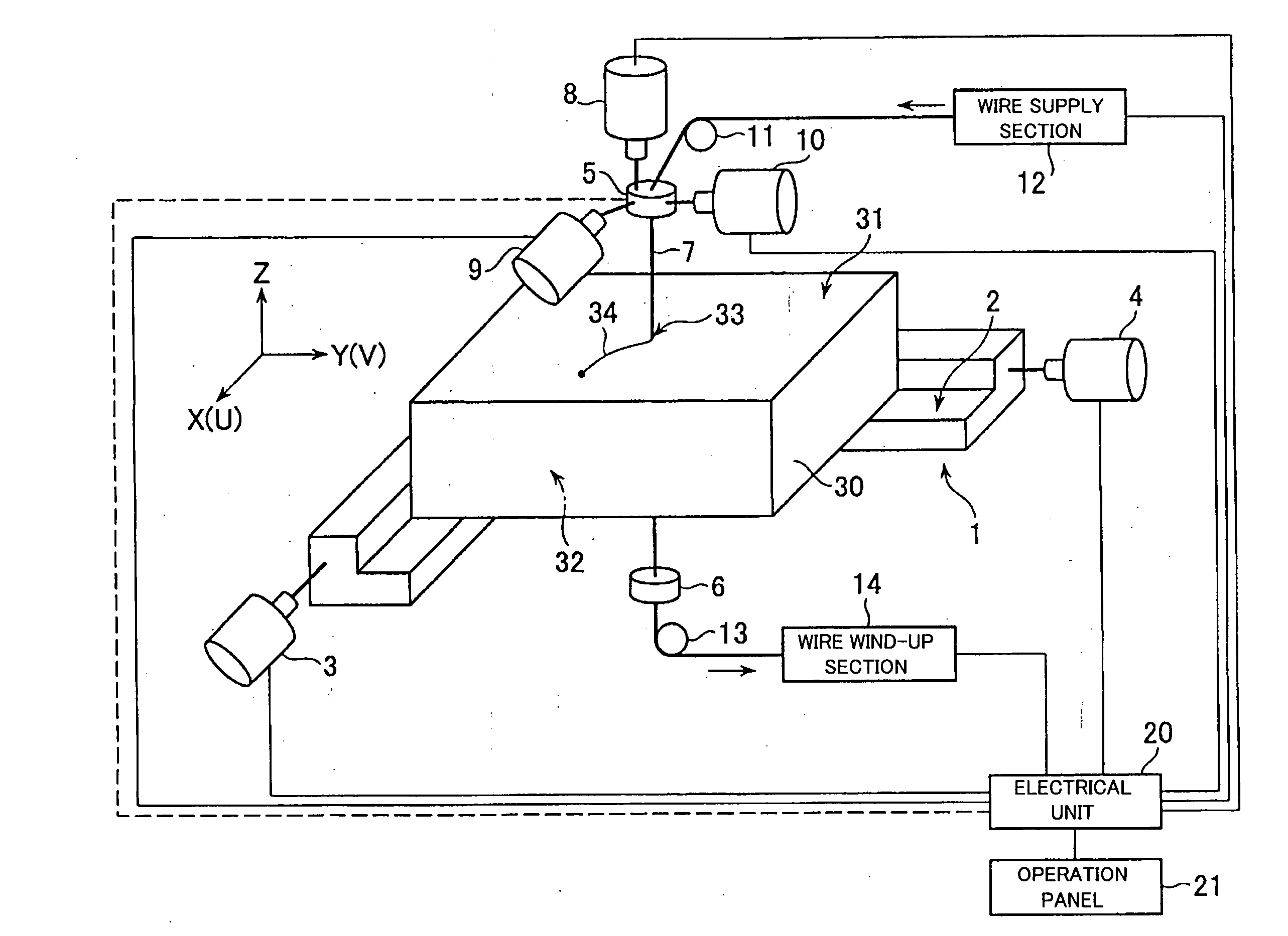
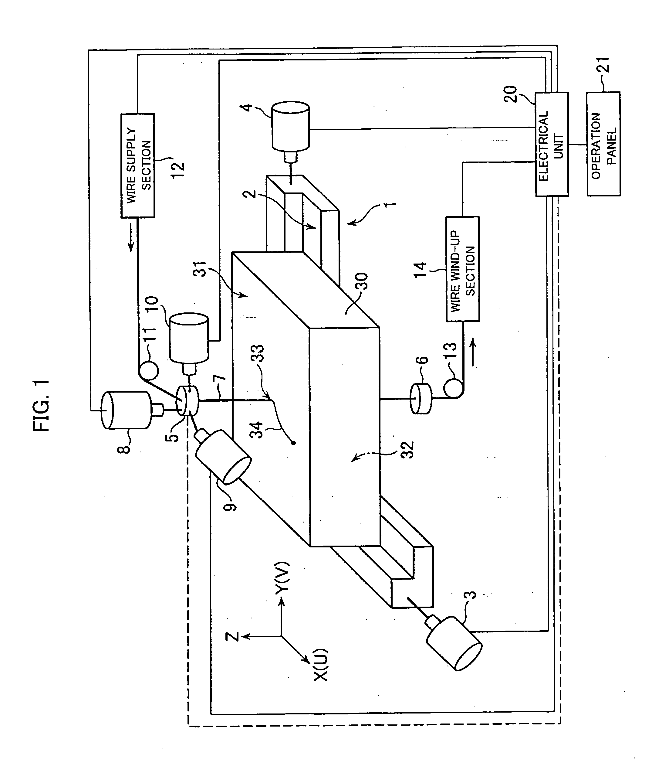
[0032]FIG. 1 is a diagram schematically showing an outline of a wire electric discharge machine according to an embodiment of the present invention. Those portions of the electric discharge machine which are concerned in machining are constructed in the same manner as those of a conventional machine. Numeral 1 denotes a workpiece table on which a workpiece 30 to be machined is set and fixed. The workpiece table 1 has a mounting surface 2 of which the flatness is highly accurate. At the time of machining, the workpiece 30 is set and fixed on the workpiece table so that its lower surface 32 is in contact with the mounting surface 2. The workpiece 30 has its entire upper surface 31 parallel to the lower surface 32. The workpiece 30 is supposed to have a surface (flat region) that is parallel to the lower surface 32. In this illustrated example, the workpiece 30 has the shape of a rectangular parallelepiped in which the entire upper surface 31 is parallel to the lower surface 32.. Alter...


PUM

PropertyMeasurementUnit
voltageaaaaaaaaaa
shapeaaaaaaaaaa
angleaaaaaaaaaa

Abstract

A wire electric discharge machine and a wire electric discharge machining method in which a workpiece set posture is compensated for an error. After a workpiece is set and fixed on a workpiece table, an upper guide measures three or more three-dimensional positions that are not situated on one straight line on an upper surface of the workpiece, utilizing detection of contact with the upper surface. A unit normal vector Nincl (Xn, Yn, Zn) is obtained, and a shift amount Δshif (ΔU, ΔV) for shift from an originally set vertical position (U0, V0) to a corrected position (Uc, Vc) is calculated. In machining, the shift amount Δshif (ΔU, ΔV) is added to the position (U0, V0) to compensate for an angle error of a machined surface, and a deviation of a machined point position caused by inclination of the workpiece is collaterally compensated for as required by correcting the upper and lower wire guides. Thus, the machined shape cannot be distorted, and the workpiece set posture error can be compensated for.

Description

BACKGROUND OF THE INVENTION [0001] 1. Field of the Invention [0002] The present invention relates to a wire electric discharge machine and a wire electric discharge machining method, and more specifically, to a wire electric discharge machine and a wire electric discharge machining method capable of appropriately coping with a machining error attributable to set posture inclination of a workpiece to be machined. [0003] 2. Description of the Related Art [0004] In general, in a wire electric discharge machine, a workpiece is set and fixed on a workpiece table that is movable within an XY-plane, and voltage is applied between a wire electrode and the workpiece to perform electric discharge machining. The wire electrode is held by upper and lower wire guides. Normally, the workpiece as an object of wire electric discharge machining has a flat lower surface to be in contact with a mounting surface of the workpiece table and a workpiece surface (whole or part of an upper surface) parallel...

Claims


Application Information

Patent Timeline
Patent Type & Authority Applications(United States)
IPC IPC(8): B23H7/10
CPCB23H7/04B23H7/065B23H2500/20
Inventor KINOSHITA, MITSUOMIYAJIMA, KEIICHIRO
Owner FANUC LTD
Why Eureka
Try Eureka