
Logging tool with response invariant to changes in borehole pressure

a technology of borehole pressure and logging tool, which is applied in the direction of nuclear radiation detection, measurement devices, instruments, etc., can solve the problems of affecting the bulk density measurement, and reducing the detection accuracy of logging tool, so as to reduce the standoff effect and minimize the void space

Active Publication Date: 2006-05-18
WEATHERFORD CANADA
View PDF6 Cites 29 Cited by
  • Summary
  • Abstract
  • Description
  • Claims
  • Application Information

AI Technical Summary

Benefits of technology

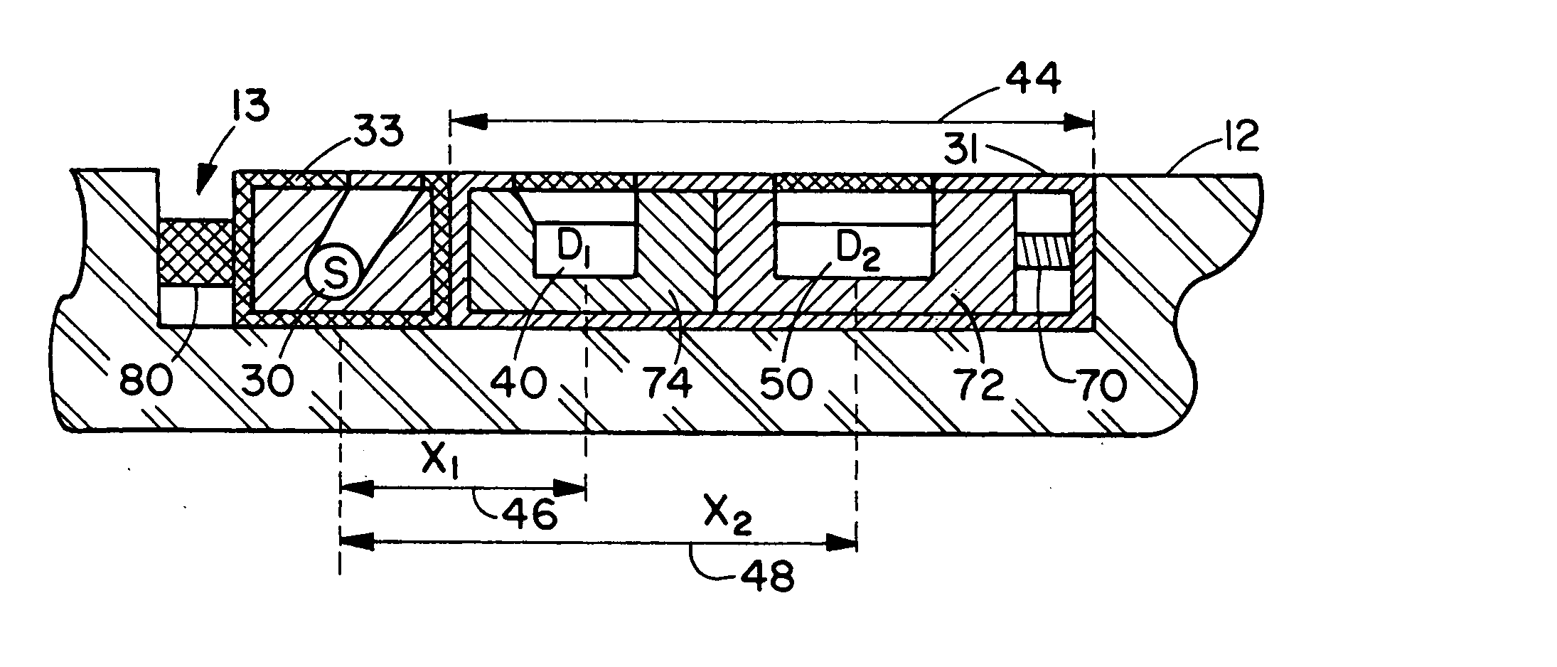
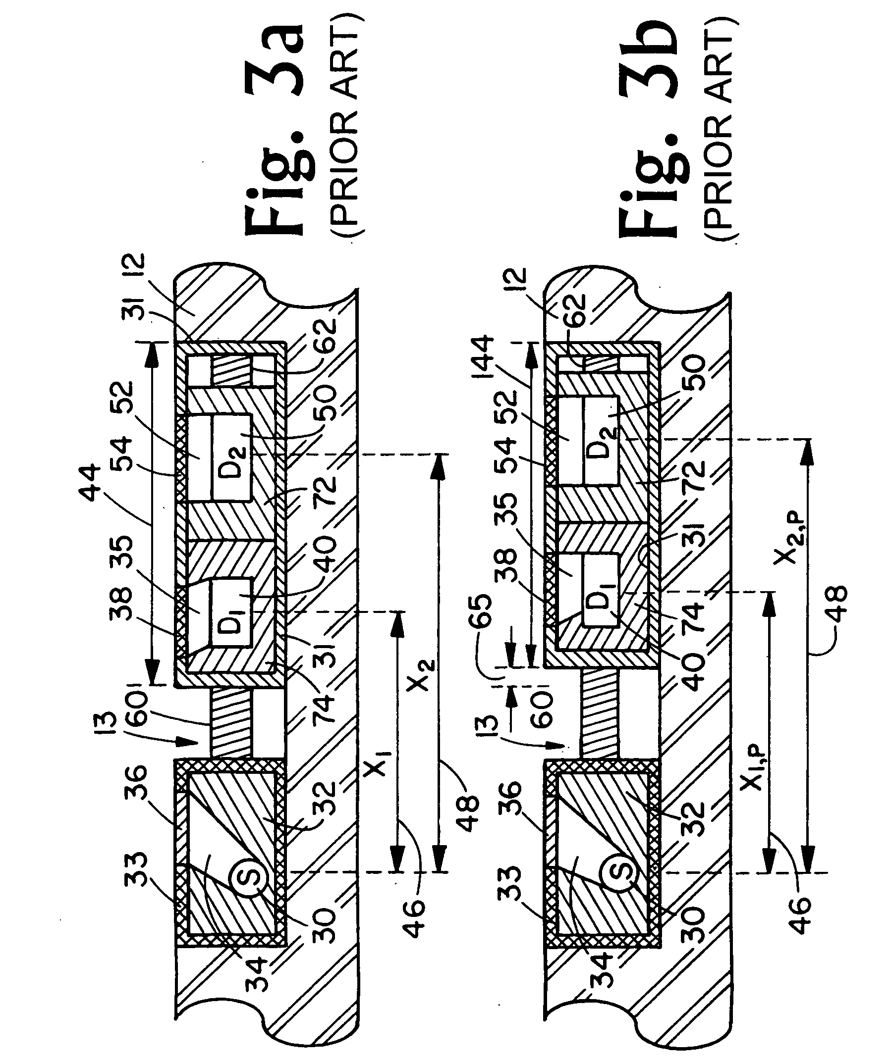
[0005] A typical wireline scatter gamma ray density tool is constructed with a gamma ray source and one or more gamma ray detectors disposed within a “pad” which is mechanically forced against the borehole wall to minimize standoff effects. The pad is typically physically robust with minimal void space. Radical changes in pressure, which are typically encountered in a borehole environment, have minimal effect on the dimensions of the pad. As a result, source-detector geometry is relatively invariant to changes in borehole pressure. The response of the system, which is typically calibrated at atmospheric pressure with a fixed source-detector geometry, is typically minimally affected by large changes in borehole pressure.

Problems solved by technology

This effect is particular detrimental to the more shallow depth of investigation nuclear logging measurements.
Mudcake and any other intervening material adversely affect the bulk density measurement.
The detector pressure housing, however, compresses under this increased pressure.
This change in source-detector spacings results in non-density related changes in count rate thereby yielding erroneous bulk density measurements.
Pressure related errors of type discussed above are typically more significant in LWD system than in wireline systems.

Method used


Image

  • Logging tool with response invariant to changes in borehole pressure
  • Logging tool with response invariant to changes in borehole pressure
  • Logging tool with response invariant to changes in borehole pressure

Examples


Embodiment Construction

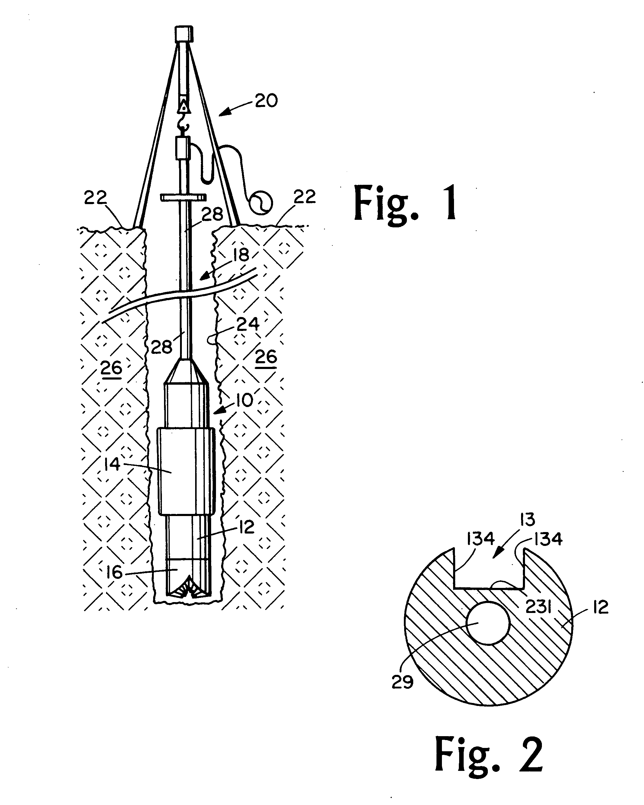
[0018] This invention is directed toward a logging system for measuring parameters of earth formation penetrated by a well borehole, wherein the response of the system is not adversely affected geometric changes induced by variations in borehole pressure. The basic concepts of the invention are applicable to any type of logging system comprising one or more energy sources, and one or more axially spaced energy sensors, where system response is a function of the relative geometry of the source and sensor. These types include nuclear, acoustic, electromagnetic, NMR systems.

[0019] The concepts of the invention are applicable to both wireline logging systems and LWD systems. As an example, concepts of the invention can be used in a LWD neutron porosity system for measuring formation porosity, wherein the system comprises a neutron source and one or more axially spaced neutron sensors commonly referred to as neutron “detectors”. As an additional example, the concepts of the invention ar...


PUM


Abstract

A logging system for measuring parameters of earth formation penetrated by a well borehole. Measurements made with the system are not adversely affected by varying pressure encountered a borehole environment. This is accomplished by the use of a main compensation element and a detector compensation element render source and detector geometry invariant to varying pressure. The system is particularly suited for nuclear LWD systems such as back scatter gamma ray density systems. The basic concepts of the system are, however, applicable to other types of nuclear measurement systems that comprise one or more radiation sources, and one or more axially spaced radiation detectors, where system response is a function of source-detector spacing. The basic concepts of the system are also applicable to other types of logging systems, such as electromagnetic and acoustic, where source (transmitter) and sensor (receiver) elements require invariant geometry in order to maximize accuracy of measurements.

Description

[0001] This invention is directed toward a logging system for measuring parameters of earth formation penetrated by a well borehole, and more particularly directed toward a system that is not adversely affected by variations in borehole pressure. The basic concepts of the invention are applicable to nuclear, acoustic, electromagnetic, nuclear magnetic resonance (NMR) and other measurement systems that comprise one or more energy sources, and one or more axially spaced energy sensors or detectors, where system response is a function of the relative geometry of the source and detector. Furthermore, the basic concepts of the invention are applicable to any type of measurement system comprising an energy source and one or more energy detectors or sensors, where system response is a function of the relative geometry of the energy source and energy detector or sensor. BACKGROUND OF THE INVENTION [0002] Logging measurement systems have been used for decades to measure various properties of...

Claims


Application Information

Patent Timeline
Patent Type & Authority Applications(United States)
IPC IPC(8): G01V5/08
CPCG01V5/08
Inventor MICKAEL, MEDHAT
Owner WEATHERFORD CANADA
Learn More