Scintillation substances (variants)

a technology of scintillation substance and scintillation substance, which is applied in the direction of polycrystalline material growth, tomography, under a protective fluid, etc., can solve the problems of large spread, significant reduction of light yield, afterglow effect, etc., and achieve the elimination of expansive losses of scintillation substance, high light yield, and reduced manufacturing cost of finished scintillation elements

Active Publication Date: 2006-04-27
ZECOTEK HLDG INC
View PDF12 Cites 62 Cited by
  • Summary
  • Abstract
  • Description
  • Claims
  • Application Information

AI Technical Summary

Benefits of technology

[0026] A task of the given invention is a creation of a new scintillation material and a method of its making. The given invention is directed on the solution of task of mass production of the large crystalline boules of scintillation materials grown by directional crystallization method. Scintillation materials should have a large density; a high light yield and a homogeneity of scintillation properties at mass production; reducing of manufacturing cost of finished scintillation elements due to small losses of crystalline substance at mechanical treatment; decreasing of time and afterglow intensity of elements having an optimal chemical composition of crystals. Stepanov's method allows to produce the scintillation

Problems solved by technology

The disadvantage of known scintillation material is the large spread of important characteristics of scintillation, namely, a light yield and an energy resolution, from crystal to crystal.
Another disadvantage is a significant reduction of light yield, when the containing LSO:Ce crystal device is operated under conditions when the temperature is above a room temperature, for example, in petroleum industry for the rock composition analyses in a borehole during the search of the new deposits.
Another disadvantage of LSO:Ce crystals is an afterglow effect, that is the prolonging fluorescence after radiation exposure, for example, the luminescence intensity of the samples described in U.S. Pat. No. 4,958,080 is reduced to decibels during ten minutes.
The drawback of patent proposed is a quality of scintillation ceramics, which is made from, so-named, stoichiometric composition of lutetium oxyorthosi-licate mixture, a stoichiometric composition is characterised by ratio of formula units of (Lu+Ce)/Si is equal exactly to 2/1.
The presence of scattering centers reduces a light yield appreci-ably.
Presence of an afterglow is very unwanted effect for some applications, for example, for an imaging system, in which the electronic part of device indicates a photon flux from the scintillation elements absorbing the gamma radiation.
Consequently, to calculate which part of a scintillation radiation is induced by some or other gamma quantum is a complicate technical task.
In this case an afterglow becomes a very undesirable effect, because it reduces an accuracy all system.
The main limitation of this group of scintillation crystals is a low light yield in comparison with the Ce-doped lutetium oxyorthosilicate, Ce2xLu2(1−x)SiO5, described above.
This substance may be utilized for detection of neutron radiation, however material is a low efficient for a gamma radiation.
However, an essential limitation of given crystal is a low density equaled to 5.5 g/cm3.
Such small density does not allow to use these crystals in three-dimensional tomographs (Fully-3D PET camera) and, especially, for MicroPET systems, because the basic requirement for scintillating crystal for these applications is an attenuation length of gamma radiation, which should be less then 1.5 cm (W. M. Moses, S. E. Derenzo “Scintillators for positron emission tomography”, Conference SCINT'95, Delft, The Netherlands (1995), LBL-37720).
These crystals are not applicable for utilization as a scintillator.
However, to our knowledge, there are no patents or publications in which these compounds were additionally doped with cerium what is necessary for an initiati

Method used


Image

  • Scintillation substances (variants)
  • Scintillation substances (variants)
  • Scintillation substances (variants)

Examples


example 1

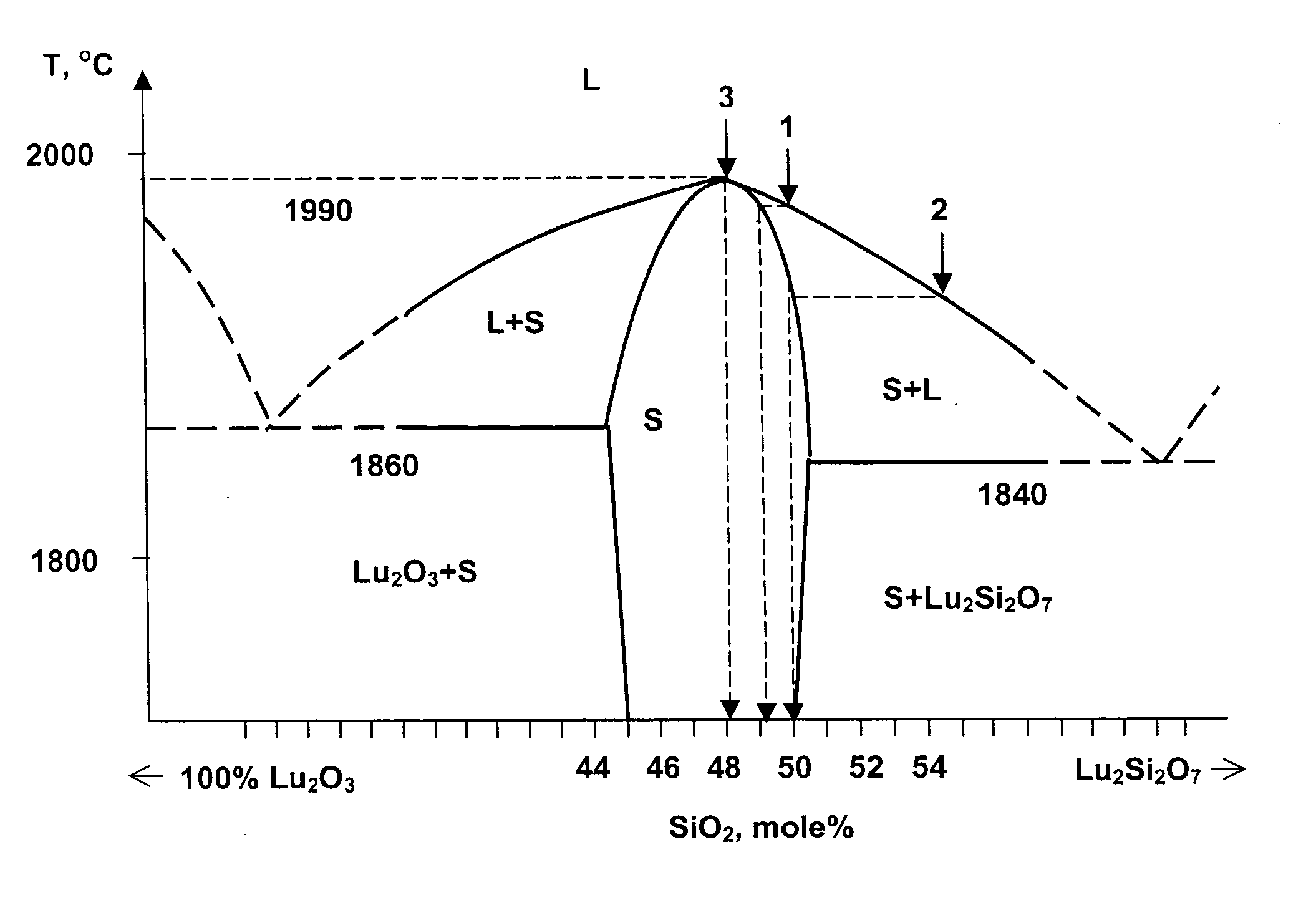
[0146] Growth of known a “reference” Ce:Lu2SiO5 crystal having the Lu / Si=2 ratio, and also the growing of crystal having a ratio of formula units of (Lu+Ce) / Si=2.061 (y=0.015), which is out of compositions range of variant No. 1 of given invention.

[0147] Due to a strong data spread about the crystal parameters published in the different issues, the parameters of commercial Ce:Lu2SiO5 crystals may be accepted as the most reliable data. The higher light output is demonstrated by the LSO crystals, having a concentration of cerium ions equaled to 0.12 at. % (or about 0.002 f. units), the chemical formula of reference crystal is Ce0.002Lu1.998SiO5. Taking into account that the segregation coefficient of the cerium ions between a melt and growing crystal is equaled about k=0.2, it is needed to charge a crucible with the starting material having a cerium concentration about 0.6 at. % (or in the formula units: 0.012 f. units). A ratio of the Lu2O3 and SiO2 oxides should be calculated takin...

example 2

[0152] A confirmation of the invention in the particular forms of implementation—the method of making of scintillation substances. To grow a large single crystal by Kyropoulos method according with the variants #1, #2, #3, and #4, an optimal scintillation substance having a composition of charge characterised by an oxides mole ratio of 51.9% (Ce2O3+Lu2O3+A2O3+Li2O) / 48.1% SiO2 was chose. At such oxides ratio, the compositions of a melt and of a crystal are characterised by a chemical formula of CexLiq+pLu2.076−p−x−zAzSi0.962O5.038−p, where A is at least one element selected from the group consisting of Gd, Sc, Y, La, Eu, Tb, x is a value between 1×10⁻⁴ f. units and 0.02 f. units, z is a value not exceeding 0.05 f. units, q+p is a value not exceeding 0.025 f. units.

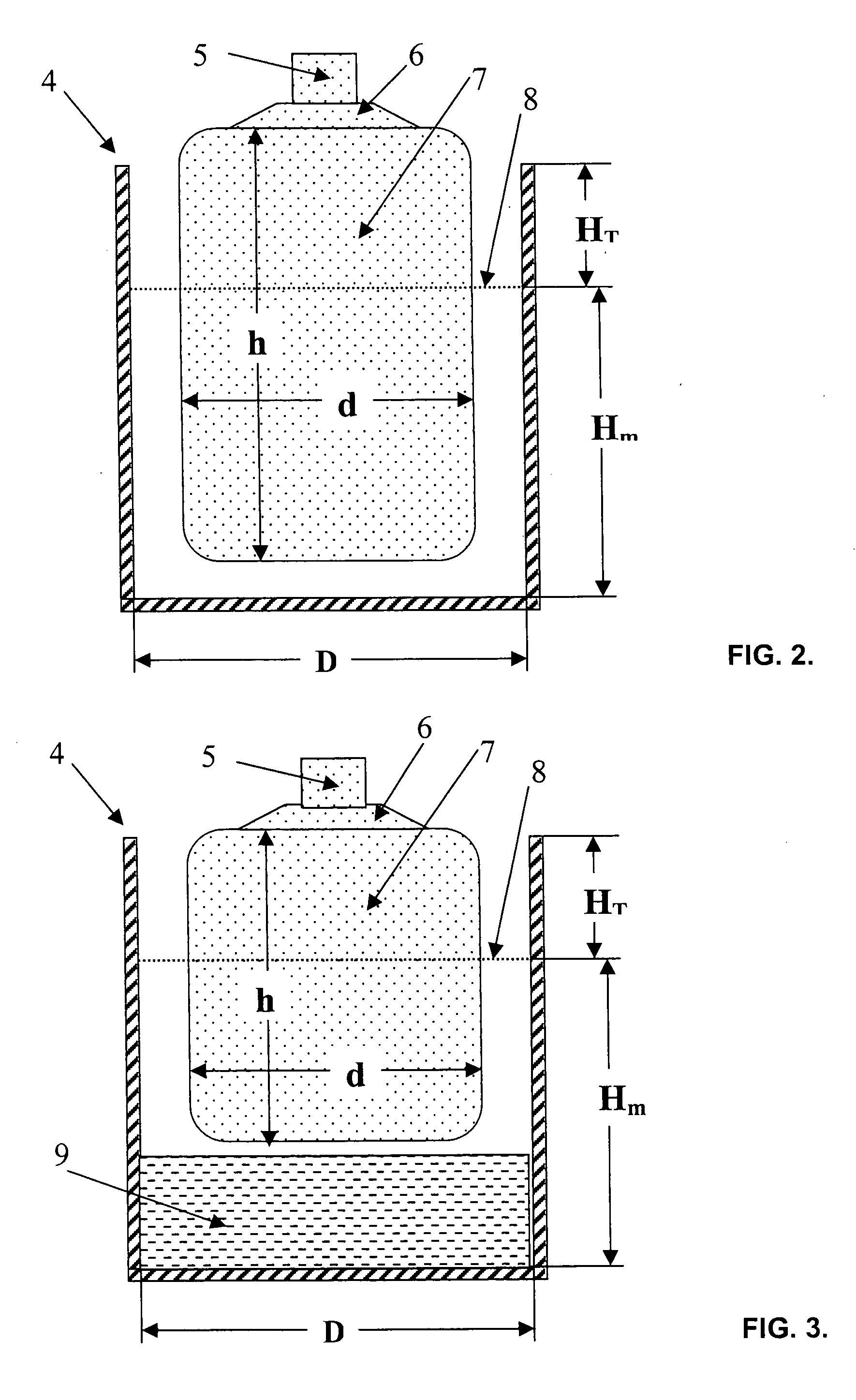
[0153] The growing of crystal 78 mm in diameter was executed from iridium crucible of 96 mm in inner diameter and about 112 mm height using the computer-controlled installation equipped with a weighing system of growing cr...

example 3

[0159] Method of making of the scintillation substances in form of scintillating ceramics on the basis of lanthanum and lutetium oxyorthosilicate differed in that the mixture of chloride water solution of Lu, La, Ce and liquid of SiCl4, are used as a starting material for preparation of charge of composition characterised by the oxides mole ratio of 51.9% (Lu2O3+La2O3+Ce2O3) / 48.1% SiO2. An ammonium carbonate water solution was added to the said mixture. Then this mixture was filtering, drain and drying. After calcination at 1400° C. the obtained oxides mixture stirred with addition of solvent and low-melting impurities, which promote an atoms diffusion through boundary of grains during a final high temperature annealing. The numerous compounds may be used as the low-melting impurities, which do not influence on an emission of Ce3+ ions. Our investigations showed that the small additives of Li, Na, K, Cs, Be, B, F, Al, S, Cl, Zn, Sc, Ga, Ge, Se, Br, I, Sn, and In ions do not lead to ...


PUM

PropertyMeasurementUnit
Fractionaaaaaaaaaa
Compositionaaaaaaaaaa
Structureaaaaaaaaaa

Abstract

Inventions relate to scintillation substances and they may be utilized in nuclear physics, medicine and oil industry for recording and measurements of X-ray, gamma-ray and alpha-ray, nondestructive testing of solid states structure, three-dimensional positron-emission tomography and X-ray computer tomography and fluorography. Substances based on silicate comprising lutetium and cerium characterised in that compositions of substances are represented by chemical formulae CexLu2+2y−xSi1−yO5+y, CexLiq+pLu2−p+2y−x−zAzSi1−yO5+y−p, CexLiq+pLu9.33−x−p−z0.67AzSi6O26−p, where A is at least one element selected from group consisting of Gd, Sc, Y, La, Eu, Tb, x is value between 1×10⁻⁴ f.units and 0.02 f.units., y is value between 0.024 f.units and 0.09 f.units, z is value does not exceeding 0.05 f.units, q is value does not exceeding 0.2 f.units, p is value does not exceeding 0.05 f.units. Achievable technical result is the scintillating substance having high density, high light yield, low afterglow, and low percentage loss during fabrication of scintillating elements.

Description

CROSS-REFERENCE TO RELATED APPLICATIONS [0001] Priory application: RU2003132127, filing dated Nov. 4, 2003; [0002] PCT / RU2004 / 000094, filing date Mar. 12, 2004. STATEMENT REGARDING FEDERALLY SPONSORED RESEARCH OR DEVELOPMENT [0003] Not applicable. REFERENCE TO SEQUENCE LISTING, A TABLE, OR A COMPUTER PROGRAM LISTING COMPACT DISK APPENDIX [0004] Not applicable. BACKGROUND OF THE INVENTION [0005] The invention is applied to scintillation materials and may be used in nuclear physics, medicine, and oil industry for recording and measuring of X-ray, gamma- and alpha- radiation; non-destructive testing of solid state structure; three-dimensional positron-electron computer tomography (PET) and X-ray computer fluorography. The relevance of the invention is that in fluoroscopy, X-ray computer tomography and PET, an introduction of new / improved scintillators has resulted in significant improvement of the image quality or / and reduced the measuring time. (“Inorganic scintillators in medical ima...

Claims


Application Information

Patent Timeline
IPC IPC(8): C09K11/66C09K11/08C30B15/00C30B21/06C30B27/02C30B28/10C30B30/04
CPCC04B35/16C04B2235/3203C04B2235/3208C04B2235/3224C04B2235/3225C04B2235/3227A61B6/4258C09K11/7774C09K11/7792C30B15/00C30B29/22C30B29/34A61B6/037C04B2235/3229C09K11/77742C09K11/77922
Inventor ZAGUMENNYI, ALEXANDER IOSIFOVICHZAVARTSEV, YURI DMITRIEVICHKUTOVOI, SERGEI ALEXANDROVICH
Owner ZECOTEK HLDG INC
Why Eureka
Try Eureka