Method and apparatus for foam molding

a foam and foam technology, applied in the field of foam molding methods, can solve the problems of poor surface appearance, low initial properties of a shaped foam, deformation of spherical cells, etc., and achieve the effect of simple structure and ease of maintenan

Inactive Publication Date: 2006-05-18
SUNSTAR GIKEN KK +1
View PDF9 Cites 13 Cited by
  • Summary
  • Abstract
  • Description
  • Claims
  • Application Information

AI Technical Summary

Benefits of technology

[0013] In the present invention, a cavity of the mold to which the foamable material is injected is placed under a pressurized condition, so that a flow of the foamable material in a region remote from an inner wall surface of the mold is suppressed, to thereby avoid problems such as cell deformation and cell continuation in this region, thus achieving uniform foaming. If desired, the method of the present invention may comprise a step of heating the cavity before or after the step of releasing the pressurized condition.
[0045] In the present invention, a shaped foam having a uniformly foamed state can be automatically produced by shifting the injection means relative to the mold. To this end, in the foam molding apparatus, the injection means may include an injection nozzle for injection of the foamable material, and the injection nozzle may be fixed to the mold or capable of free movement relative to the mold. With this arrangement, the foam molding apparatus can be made simple in structure. Further, an automatic production system for producing a shaped foam and ease of maintenance can be achieved. In the present invention, the injection nozzle may be fixed, with an immovable injection opening (a distal end of the nozzle). Otherwise, the injection nozzle itself may be fixed, with the injection opening being vertically movable or capable of oscillation.

Problems solved by technology

However, during flow of this foamable material, spherical cells may be deformed, or may become enlarged due to continuation between cells.
This results in a poor surface appearance and low initial properties of a shaped foam, and durability of the foam may also be low due to a high degree of compressive permanent deformation.
However, when use is made of a large or elongated mold or a mold having a complex shape, it is difficult to shift an injection nozzle, so that the above method cannot be readily conducted.
Further, when an injection nozzle is to be shifted, it is difficult to conduct an automatic or continuous operation for molding a foamable material.

Method used


Image

  • Method and apparatus for foam molding
  • Method and apparatus for foam molding
  • Method and apparatus for foam molding

Examples


Embodiment Construction

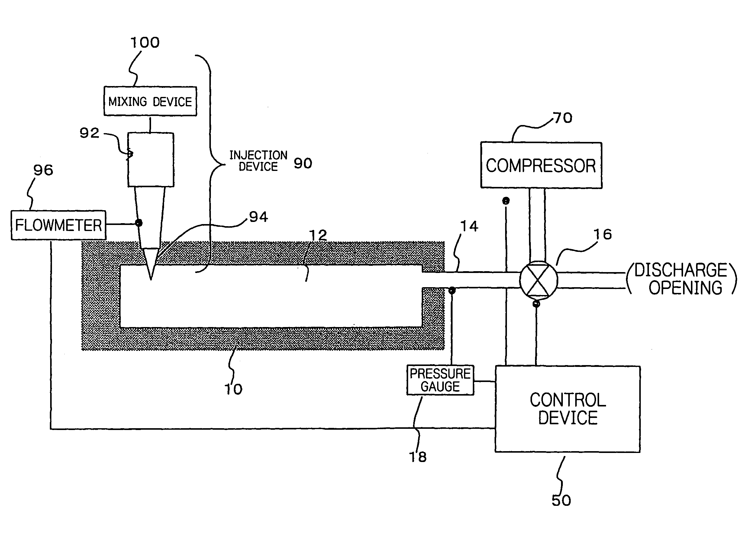
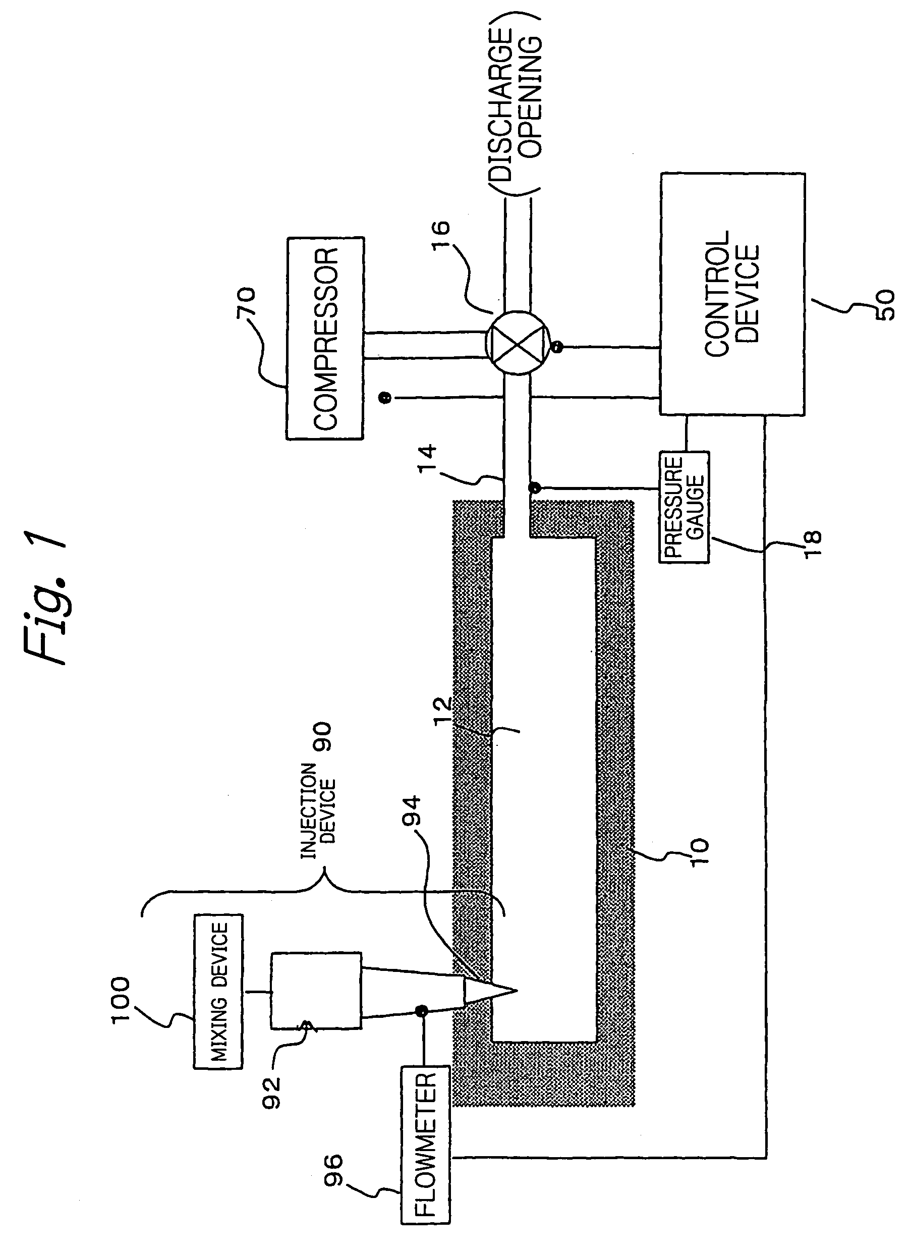
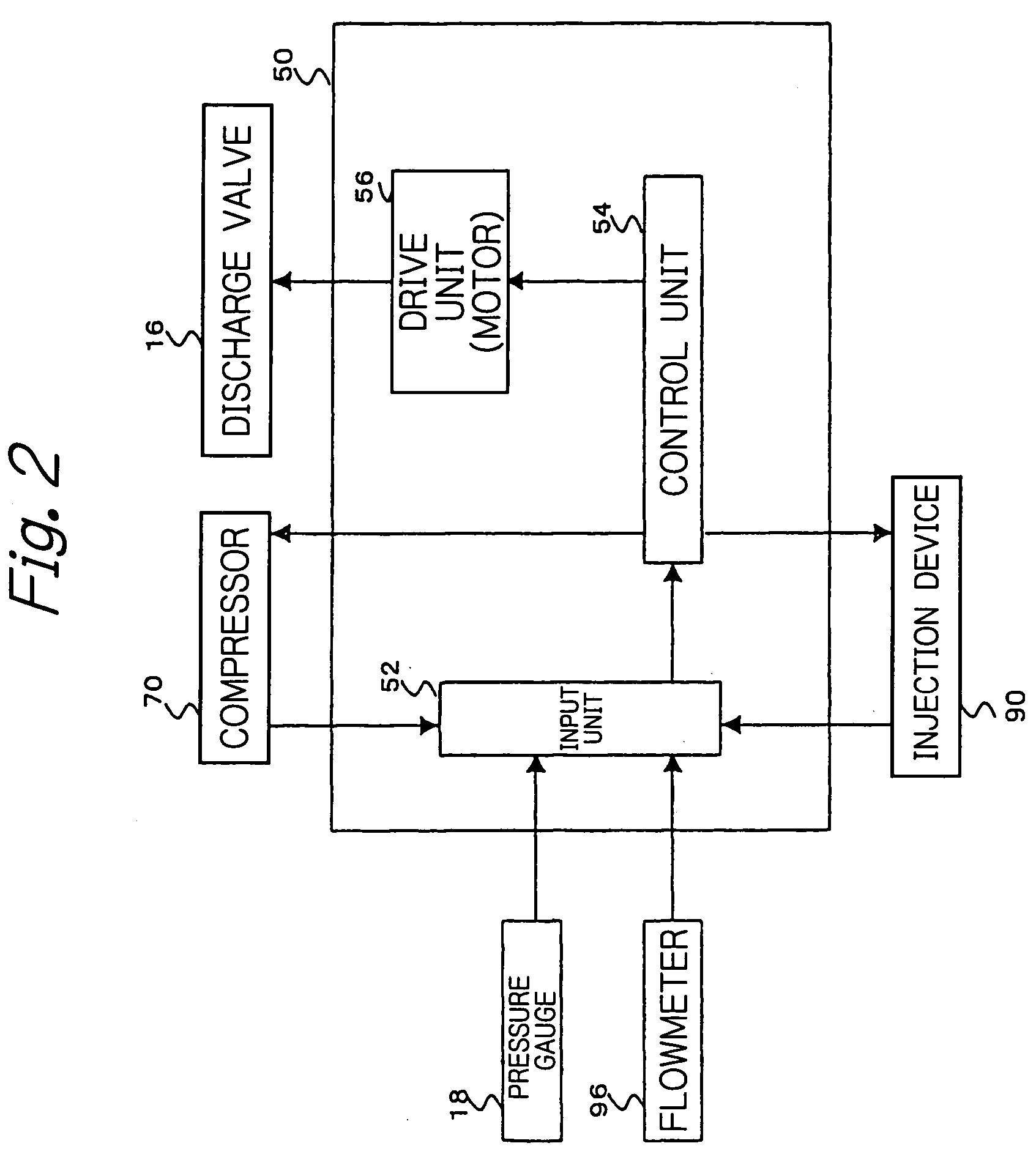
[0071] Hereinbelow, referring to the drawings, description is made with regard to a foam molding apparatus according to an embodiment of the present invention. FIG. 1 is a schematic illustration of a general construction of the foam molding apparatus. FIG. 2 is a functional block diagram of a control device. FIG. 3 shows a general construction of a mixing device.

(1) Foamable Material

[0072] A heat curable composition used as a foamable material in an embodiment of the present invention is prepared by mixing, with a gas, a material to be foamed which contains polyurethane as a main component. A composition of the material to be foamed is obtained as follows. First, to obtain a polyurethane prepolymer, polyether polyol and diphenylmethane diisocyanate are subjected to a reaction at 80° C. for 2 hours, to thereby obtain an urethane prepolymer having a terminal active isocyanate group which has a terminal NCO content of 2.4% and a viscosity of 100000 cps / 20° C. To obtain an inactivate...


PUM

PropertyMeasurementUnit
melting pointaaaaaaaaaa
particle sizeaaaaaaaaaa

Abstract

It is an object of the present invention to provide a foam molding method for foaming and molding a foamable material, which is free from problems, such as deformation of or continuation between closed cells. To achieve this object, there is provided a foam molding method for foaming a foamable material, comprising the steps of providing a mold having a cavity, placing the cavity of the mold under a pressurized condition, foaming the foamable material in the cavity of the mold under the pressurized condition, thus appropriately controlling foaming of the foamable material, and releasing the pressurized condition of the cavity of the mold.

Description

TECHNICAL FIELD [0001] The present invention relates to a foam molding method and to an apparatus used therefor. Specifically, the present invention relates to a method for molding a foamable material into a predetermined shape, in which the foamable material is injected into a mold and foamed therein, to thereby fill a cavity of the mold with the foamed material. The present invention also relates to an apparatus used for carrying out the method. TECHNICAL BACKGROUND [0002] In a conventional technique of this type, it has been desired to obtain a shaped foam having a number of cells formed therein, by mechanically mixing a material with a gas, to thereby form a foamable material, and injecting the foamable material into a mold, followed by removal of the mold. When such a gas-containing foamable material is injected into a mold, the gas is released into an atmosphere (normally set to atmospheric pressure) in the mold cavity. Therefore, the gas expands in the foamable material almos...

Claims


Application Information

Patent Timeline
Patent Type & Authority Applications(United States)
IPC IPC(8): B29C44/60B29C33/10B29C44/10
CPCB29C33/10B29C44/086B29C44/10B29C44/3403B29C44/3442B29C44/5627B29C44/586B29C44/60
Inventor TANAKA, SATOSHITAKADA, MASAHARUJOYASHIKI, HISASHI
Owner SUNSTAR GIKEN KK
Why Eureka
Try Eureka