Injection perform transfer improvement

a technology of injection and transfer delay, which is applied in the direction of dough shaping, manufacturing tools, applications, etc., can solve the problems of delay in the tube's ability to build a vacuum, the preform is conical in shape and does not transfer well, and the preform is slow to transfer, so as to eliminate the addition of energy-consuming and maintenance-intensive devices, the effect of cost-effectiveness

Inactive Publication Date: 2006-05-18
GRAHAM PACKAGING CO LP
View PDF2 Cites 0 Cited by
  • Summary
  • Abstract
  • Description
  • Claims
  • Application Information

AI Technical Summary

Benefits of technology

[0015] The present invention improves upon devices and methods available in the art by eliminating transfer delays without the addition of energy-consuming and maintenance-intensive devices. The take-off tube assembly of the present invention is easily adapted for use with a variety of preforms, particularly those that are conical in shape or tapered. Furthermore, the invention is cost effective.

Problems solved by technology

For some containers, preforms are conical in shape and do not transfer well.
This is due to the distance between the tapered end of the preform and the walls at the open end of the receptacle of the take-off tube, which causes a delay in the tube's ability to build a vacuum.
This delay slows the transfer of the preform, since it takes longer to create the vacuum force, or draw, that pulls the preform into the receptacle.
The excessive distance A′ creates a delay in the build-up of the vacuum, causing a delay in the transfer process.
An attempted solution has been to use air to blow the preform into the tube, but this technique has experienced limited success and presents maintenance issues.
Unfortunately this technique is very expensive.

Method used


Image

  • Injection perform transfer improvement
  • Injection perform transfer improvement
  • Injection perform transfer improvement

Examples


Embodiment Construction

[0026] Embodiments of the invention are discussed in detail below. In describing embodiments, specific terminology is employed for the sake of clarity. However, the invention is not intended to be limited to the specific terminology so selected. While specific exemplary embodiments are discussed, it should be understood that this is done for illustration purposes only. A person skilled in the relevant art will recognize that other components and configurations can be used without parting from the spirit and scope of the invention. All references cited herein are incorporated by reference as if each had been individually incorporated.

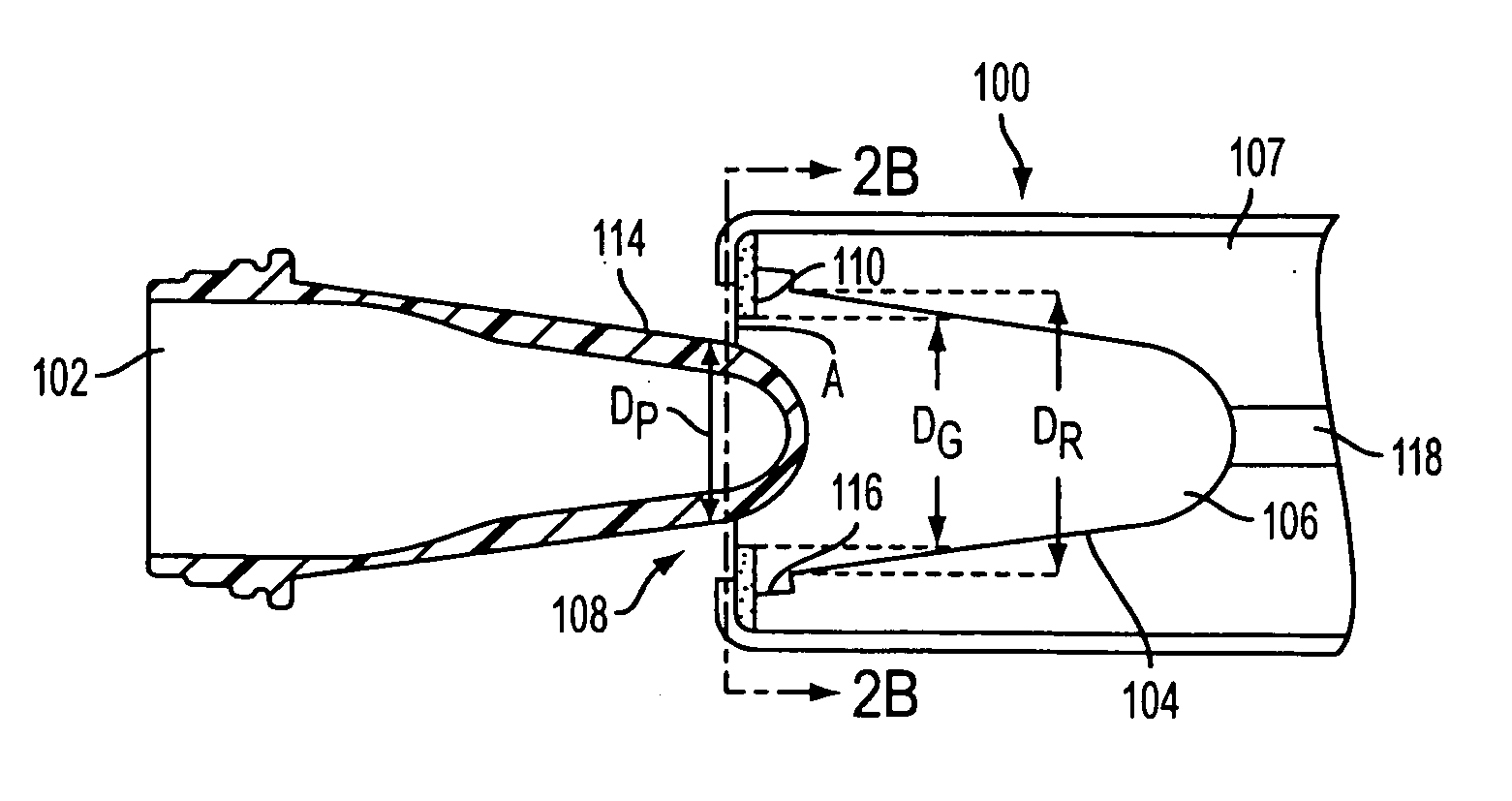
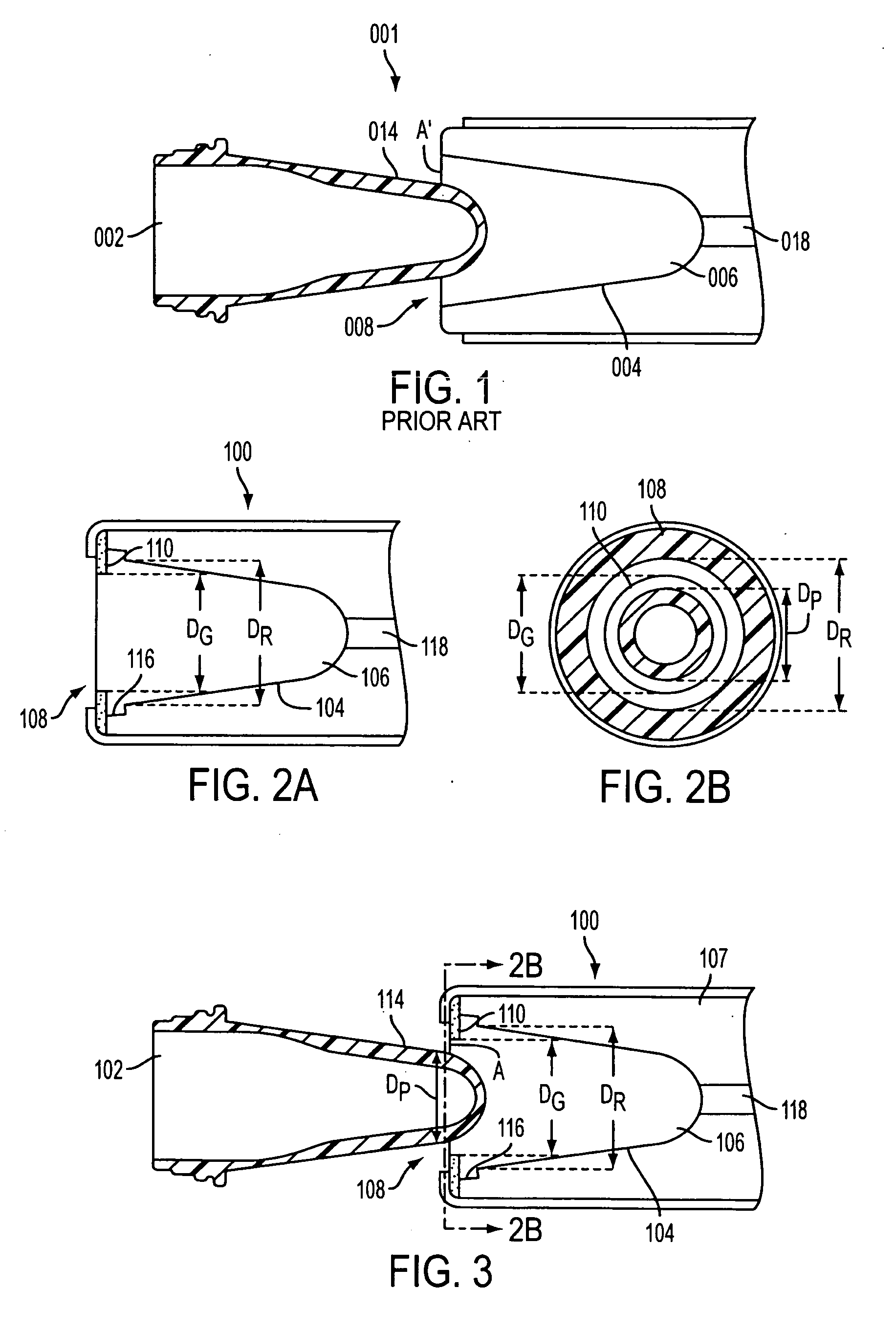
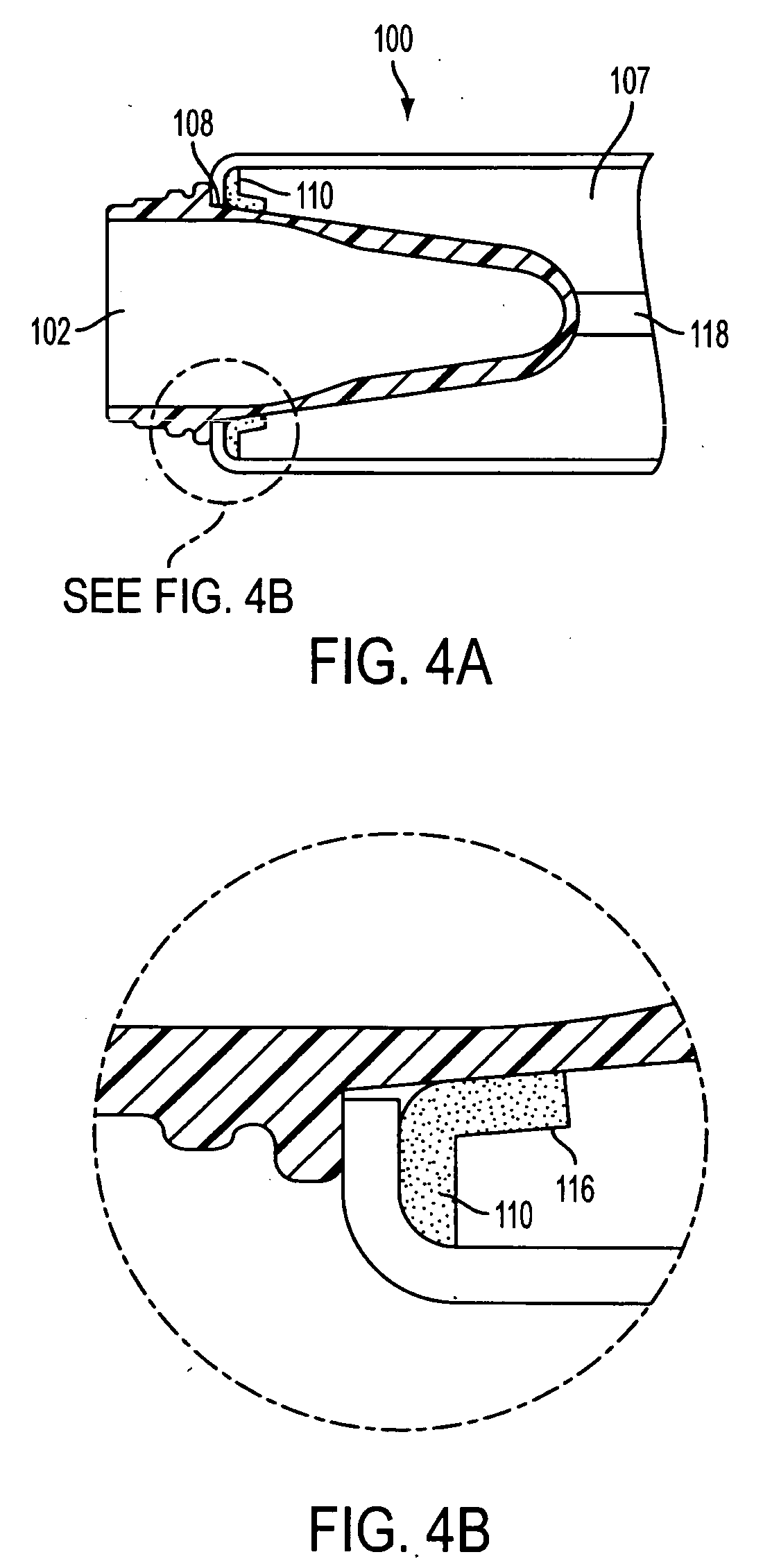
[0027] As depicted in the exemplary embodiment shown in FIG. 2A, the present invention is a take-off tube assembly 100 for transferring a preform 102 (See FIG. 3). The take-off tube assembly 100 includes walls 104 defining a receptacle 106, and a channel 107 within those walls for containing a cooling substance. Generally the cooling substance is water,...


PUM

PropertyMeasurementUnit
cross-sectional areaaaaaaaaaaa
areaaaaaaaaaaa
vacuumaaaaaaaaaa

Abstract

A take-off tube assembly for transferring a preform and methods of use are discussed. The assembly has walls defining a receptacle, and the receptacle has an open end with a cross sectional area. A preform guide is located along the walls of the receptacle, the preform guide having an open end with a cross sectional area smaller than the cross sectional area of the receptacle. A vacuum inlet is also be present, allowing connection of the assembly to a vacuum so that a vacuum draw can facilitate transfer of the preform to the take-off tube.

Description

BACKGROUND OF THE INVENTION [0001] 1. Field of the Invention [0002] The present invention relates generally to an apparatus for transferring a preform, and more particularly a take-off tube assembly comprising a receptacle that includes a preform guide and is adapted to receive the preform. [0003] 2. Background Information [0004] Injection blow molding can be a two step process that requires the use of an injection molded preform to develop the final product. As part of the blow molding process, injection molded preforms must be removed from the mold. This can be accomplished by transferring the preform from the mold to a take-off tube. A cylindrical receptacle within the tube is used to receive the preform. The take-off tube assembly also comprises a vacuum inlet so that a vacuum can be connected, thus creating sufficient force to pull the preform into the receptacle. Once transfer is complete, the preform can be used in further applications. [0005] The shape of preforms varies and...

Claims


Application Information

Patent Timeline
Patent Type & Authority Applications(United States)
IPC IPC(8): B28B7/12
CPCB29C45/4225B29C45/7207B29C49/4205B29C2035/1616B29C2045/7214B29C2045/7242B29C2791/006B29K2105/258B29C49/42077B29C49/681
Inventor JOHNSTON, ROBERT
Owner GRAHAM PACKAGING CO LP
Why Eureka
Try Eureka