Method and apparatus for field drift compensation of a superconducting magnet

a superconducting magnet and field drift compensation technology, applied in the field of magnetic coils, can solve the problems of undesirable artifacts in image data, inability to automatically compensate active shielded magnets (i.e., via lens's law), and inability to compensate active shielded magnets

Inactive Publication Date: 2006-05-18
GENERAL ELECTRIC CO
View PDF12 Cites 11 Cited by
  • Summary
  • Abstract
  • Description
  • Claims
  • Application Information

AI Technical Summary

Benefits of technology

[0008] The above discussed and other drawbacks and deficiencies are overcome or alleviated by an adjustable magnetic field compensation system with micro flux adjusting capability for magnet system B0 field adjustment by using a secondary low inductance superconducting coils. The method for magnetic field drift compensation for a superconducting magnet system includes electrically coupling a micro-flux injection system to a secondary B0 superconducting coil in a seconda...

Problems solved by technology

Unlike conventional magnets, an actively shielded magnet is unable to automatically compensate (i.e., via Lens's Law) for the magnetic disturbances to the B0 field in the imaging volume due to external magnetic sources.
If the static magnetic field is significantly inhomogeneous, undesirable artifacts will occur in the image data.
However, even when extraordinary steps are taken to ensure proper construction of the main coil and magnet field uniformity, some spatial field unif...

Method used


Image

  • Method and apparatus for field drift compensation of a superconducting magnet
  • Method and apparatus for field drift compensation of a superconducting magnet
  • Method and apparatus for field drift compensation of a superconducting magnet

Examples


Embodiment Construction

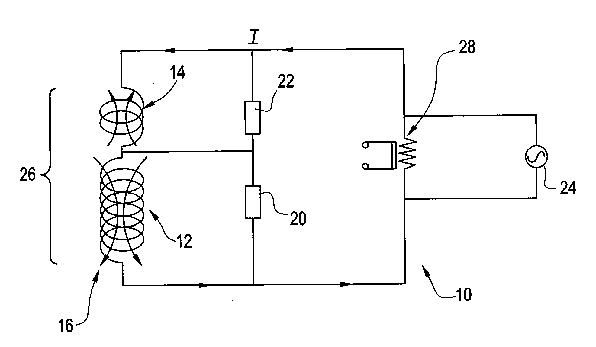
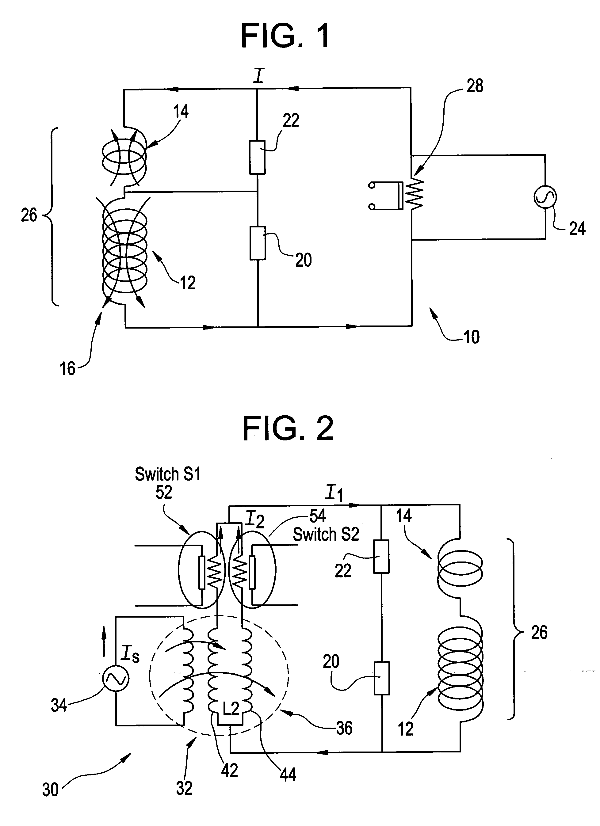
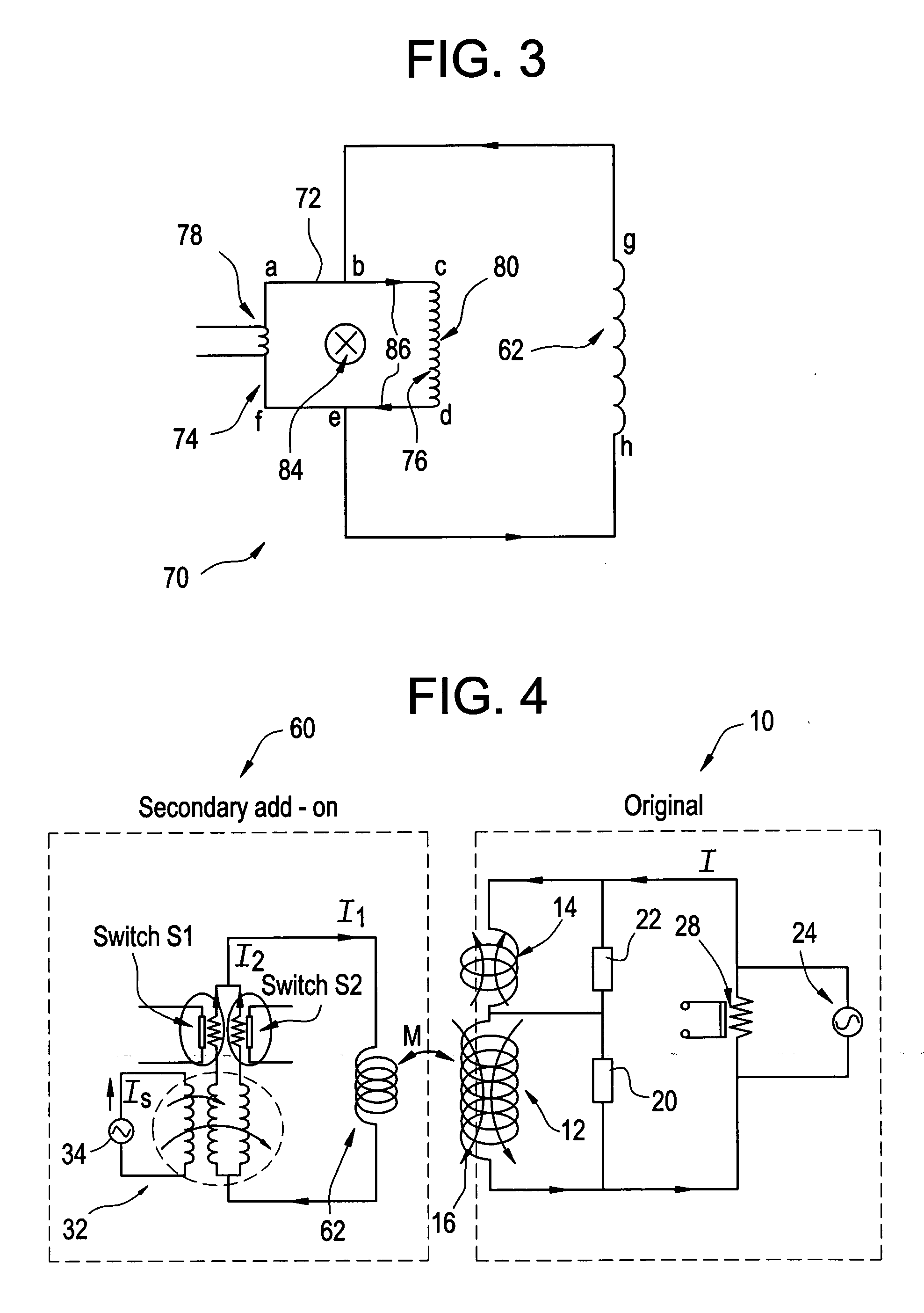
[0018] Referring to FIG. 1, a simplified schematic circuit diagram with a quench protection circuit 10 is shown for an actively shielded MRI magnet having a main coil 12, and a bucking or shielding coil 14. Coil 12 and 14 produce a homogeneous field 16 in the image volume and bucking coil 14 also reduces fringe fields. Connected across magnet coils 12 and 14 respectively, and in parallel therewith, are quench protection resistive load and quench heaters circuits 20, 22. The circuit 10 contains a power supply (i.e. current supply) 24 for ramping up the superconductive magnet coils assembly 26 and a superconducting persistent switch 28. The superconducting switch 28 is used to transfer between a persistent superconducting operating mode and a non-persistent superconducting operating mode.

[0019] Power supply 24 is a DC power supply with removable leads, such that once a current (I) is provided to circuit 10, and the magnet system is in persistent mode, the power supply 24 may be remov...


PUM


Abstract

A method and apparatus for magnetic field drift compensation for a superconducting magnet system includes electrically coupling a micro-flux injection system to a secondary B0 superconducting coil in a secondary compensation circuit; magnetically coupling the secondary compensation circuit to the superconducting magnet via the secondary B0 superconducting coil; switching the micro-flux injection system on and off either thermally or magnetically to induce a first current from a flux coil of the secondary compensation circuit into the secondary B0 superconducting coil producing a secondary field to compensate magnet field drift of the superconducting magnet.

Description

BACKGROUND OF THE INVENTION [0001] The present invention relates to magnetic coils for producing highly uniform magnetic fields, such as those required for magnetic resonance imaging, and particularly to a method and apparatus for compensating for magnetic field drift of a superconducting coil. [0002] As is well known, a magnet coil wound of superconductive material can be made superconducting by placing it in an extremely cold environment. For example, a coil may be made superconducting by enclosing it in a cryostat or pressure vessel containing a cryogen. The extreme cold enables the superconducting wires to be operated in the superconducting state. In this state, the resistance of the wires is practically zero. To introduce a current flow through the coils, a power source is initially connected to the coils for a short time period. In the superconducting state, the current will continue to flow through the coils, thereby maintaining a strong magnetic field. In other words, becaus...

Claims


Application Information

Patent Timeline
IPC IPC(8): G01V3/00
CPCG01R33/3815H01F6/008
Inventor SHEN, WEIJUN
Owner GENERAL ELECTRIC CO
Why Eureka
Try Eureka