Digital potentiometer

a digital potentiometer and potentiometer technology, applied in the direction of resistors, adjustable resistors, electrical equipment, etc., can solve the problems of resistance precision and drift associated with mechanical analog potentiometers, fet devices as taught by the prior art cannot respond to alternating currents or reverse currents, and fet devices that cannot work with this potentiometer

Inactive Publication Date: 2006-05-18
AVISTART ENTERPRISES
View PDF7 Cites 9 Cited by
  • Summary
  • Abstract
  • Description
  • Claims
  • Application Information

AI Technical Summary

Benefits of technology

[0007] This invention utilizes switches (preferably mechanical relays) which are controlled in any combination of on-off states by a computer. The switches are generally in the form of relays because the invention is not dependent upon field effect transistors. FET devices as taught by the prior art cannot respond to alternating currents or reverse currents.

Problems solved by technology

FET devices as taught by the prior art cannot respond to alternating currents or reverse currents.
FET's will not work with this potentiometer because they conduct in only one direction and therefore cannot respond to alternating current measurements or alternating current control.
The first problem is resistance precision and drift associated with mechanical analog potentiometers.
A second problem with prior art devices is inability to handle zero-referenced AC signals as with semiconductor MOSFET potentiometers.
A third problem is that high-current applications have only been controlled by mechanical analog potentiometers.

Method used


Image

  • Digital potentiometer
  • Digital potentiometer
  • Digital potentiometer

Examples


Embodiment Construction

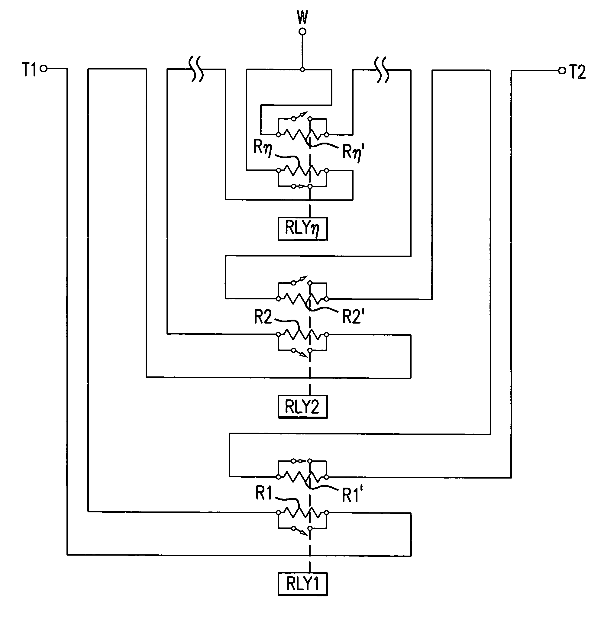
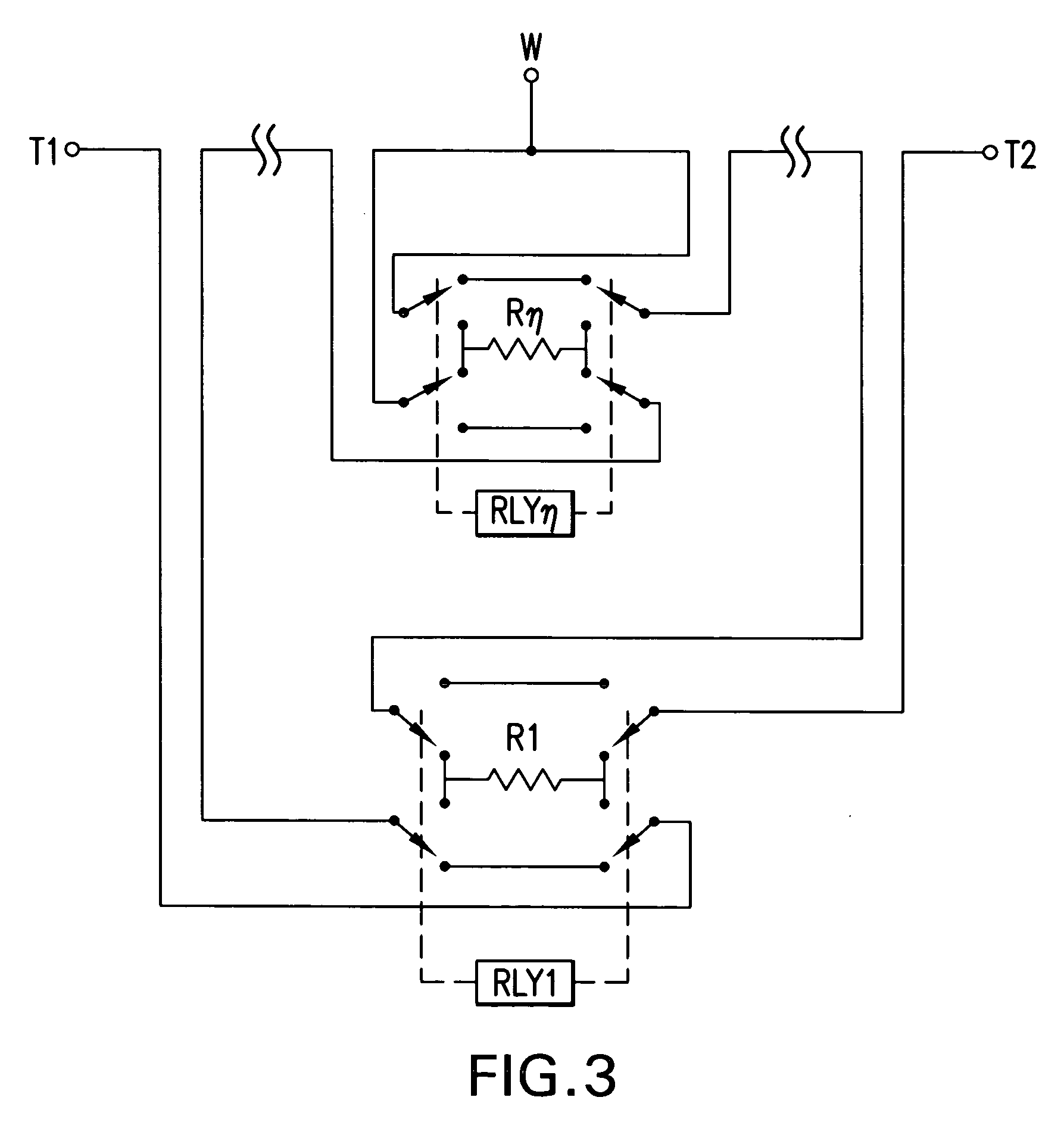
[0028] The invention may use a serial port to precisely set resistance values using a defined control sequence sent to the potentiometer device over a serial port. Actual switching of resistor shorts or resistor position from one side of a wiper to another can be easily implemented by relays controlled by the computerized sequence. This device when fully implemented may display the requested resistance on a computer screen or a display device incorporated into a test instrument. The potentiometer can be paired with a “slave” potentiometer to create a Wheatstone bridge circuit that works using either AC or DC signals.

[0029] The potentiometer of this invention which utilizes resistors and relays will have electrical characteristics exactly like a standard analog potentiometer in that there is no need to consider the polarity or absolute sign of the signal applied. In this invention, the speed at which the resistance can be changed is limited by the speed of the micro-mechanical relay...


PUM


Abstract

A variable potentiometer with a wiper terminal and first and second terminals has relay switches for shorting or for unshorting resistors. When resistance is reduced between the wiper and one of said terminals, resistance is increased between the wiper and another terminal. In one embodiment two strings of resistors with the same nominal values are used between the wiper and the terminals. In another embodiment, a single string of resistors are used and are switched into either the electrical connection between the wiper and the first terminal or between the wiper and the second terminal. When resistance is lowered between the wiper and one of said first or second terminals a first resistor is replaced with a first short circuit and when resistance is increased between said wiper and another of said first and second terminals a second short circuit is replaced with the first resistor.

Description

TECHNICAL FIELD OF THE INVENTION [0001] This invention relates to potentiometer circuits of the type where there is a wiper and first and second terminals at each end of a resistance between the terminals. In early potentiometers, the resistance may have been wire wound or a resistance pad. In these devices a wiper moved along the resistor and picked off the voltage from the resistor. These devices find application in high current applications. As a practical matter, impedance at the wiper would be high which would prevent current drain at the wiper. In these prior art devices, the wiper is physically moved by an operator. PRIOR ART [0002] Prior art devices generally utilize a resistor chain with taps between each pair of resistors. U.S. Pat. No. 4,849,903 to Fletcher and Ross is hereby incorporated by reference and teaches a digitally controlled variable resistor for effecting and presenting a selected electrical resistance. Resistance may be changed along a string of resistors by ...

Claims


Application Information

Patent Timeline
Patent Type & Authority Applications(United States)
IPC IPC(8): H01C10/00
CPCH01C10/08
Inventor KESSLER, GARYGARCIA, MICHAELMIGLIORI, ALBERT
Owner AVISTART ENTERPRISES
Why Eureka
Try Eureka