Optical information-recording medium

a technology of optical information and recording medium, which is applied in the field of optical information recording medium, can solve the problems of not being able to correctly reproduce bca information, the recording layer and the reflective film are subjected to exfoliation, etc., and achieve the effect of suppressing the fluctuation of amplitud

Inactive Publication Date: 2006-05-18
HITACHT MAXELL LTD
View PDF25 Cites 22 Cited by
  • Summary
  • Abstract
  • Description
  • Claims
  • Application Information

AI Technical Summary

Benefits of technology

[0020] When the concave / convex pattern is formed in BCA to satisfy any one of the expressions (1) to (4) described above, then the dye material remains at the emboss pit portion and the groove portion of BCA, and the film thickness of the recording layer on BCA is sufficiently thick, even when the recording layer is coated and formed, for example, by the spin coat method to have such a film thickness that the recording characteristic of the user information area is optimum. When the concave / convex pattern is formed in BCA to satisfy any one of the expressions (1) to (4) described above, then the area of the land portion other than the groove portion and / or the emboss pit portion of BCA is smaller than the optical resolution λ / (2·NA) of the optical disk drive to be used for the recording and reproduction, and the area has a completely indistinguishable size. In this situation, when the reproducing light beam is radiated on BCA without performing the tracking, the reproducing light beam is radiated to traverse the groove portion and the land portion of BCA due to the eccentricity of the medium. However, the area of the land portion is smaller than the optical resolution. Therefore, the reproduced signal is obtained from BCA, the reproduced signal being formed by averaging the reproduced signal of the land portion at which the signal amplitude is scarcely obtained and the reproduced signal of the groove portion and the emboss pit portion at which the sufficient signal amplitude is obtained. As a result, it is possible to suppress the amplitude fluctuation of the BCA reproduced signal.
[0021] When the concave / convex pattern is formed in BCA to satisfy any one of the expressions (1) to (4) described above, then the following relationship holds between a minimum amplitude Imin of a reproduced signal of BCA and an amplitude CT of a cross-track signal, and thus it is possible to reproduce the BCA information with a satisfactory signal quality: Imin>CT. In the case of the optical information-recording medium of the present invention, the concave / convex pattern is also formed in BCA. Therefore, the reproduced signal level, which is obtained from the groove and the emboss pit array when the BCA information is reproduced, is slightly different from the reproduced signal level which is obtained form the land portion other than the areas as described above. The influence of the cross-track signal is more or less exerted. However, according to a verifying experiment performed by the inventors, when the concave / convex pattern of BCA is formed to satisfy any one of the expressions (1) to (4), the minimum amplitude Imin of the reproduced signal is larger than the amplitude CT of the cross-track signal, even when the influence of the cross-track signal is more or less exerted when the information of BCA is reproduced without performing the tracking. Therefore, it is possible to reproduce the BCA information more correctly. The phrase “amplitude of the cross-track signal” referred to in this specification is the larger fluctuation amount of the fluctuation amount of the non-recorded level of the reproduced signal obtained from BCA (signal level obtained from the non-recorded portion of BCA) and the fluctuation amount of the recorded level (signal level obtained from the recorded portion of BCA).
[0022] In the optical information-recording medium of the present invention, when the concave / convex pattern is formed in BCA to satisfy any one of the expressions (1) to (4), the following relationship holds between a higher reflectance RH and a lower reflectance RL of reflectances of a recorded portion and a non-recorded portion of BCA, even when the information of BCA is reproduced without performing any tracking: (RH−RL) / RH≧0.2. That is, the modulation factor of the reproduced signal of BCA is not less than 20%, and it is possible to obtain the BCA reproduced signal having the satisfactory signal quality.
[0030] According to the optical information-recording medium of the present invention, the concave / convex pattern of BCA is formed to have the shape which satisfies any one of the expressions (1) to (4), while the concave / convex pattern of BCA is different from the concave / convex pattern formed in the user information area. Therefore, the recording layer, which has the film thickness of such an extent that the BCA reproduced signal is sufficiently obtained, can be formed on BCA. Further, even when the BCA information is reproduced without performing any tracking control, the minimum amplitude value of the BCA reproduced signal can be made larger than the amplitude value of the cross-track signal (amplitude fluctuation can be suppressed). Thus, it is possible to reproduce the BCA information with the satisfactory signal quality.

Problems solved by technology

In the case of DVD-R which is a write-once type optical information-recording medium, a problem arises such that the recording layer and the reflective film are subjected to the exfoliation, if the reflective film is removed by means of the YAG laser in the same manner as in DVD-ROM.
As a result, it was not possible to correctly reproduce the BCA information.

Method used


Image

  • Optical information-recording medium
  • Optical information-recording medium
  • Optical information-recording medium

Examples


example 1

Preparation of Optical Information-Recording Medium

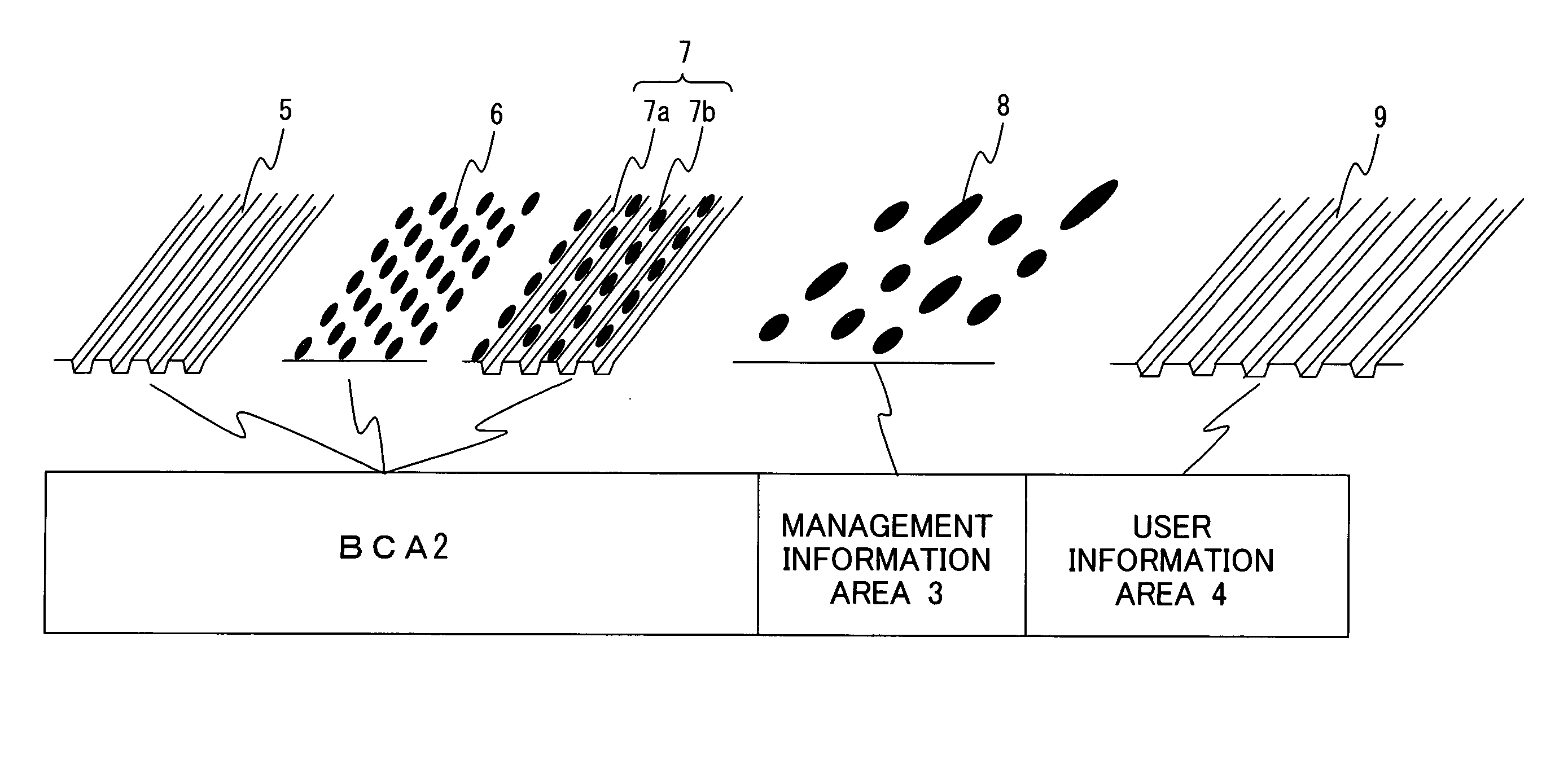
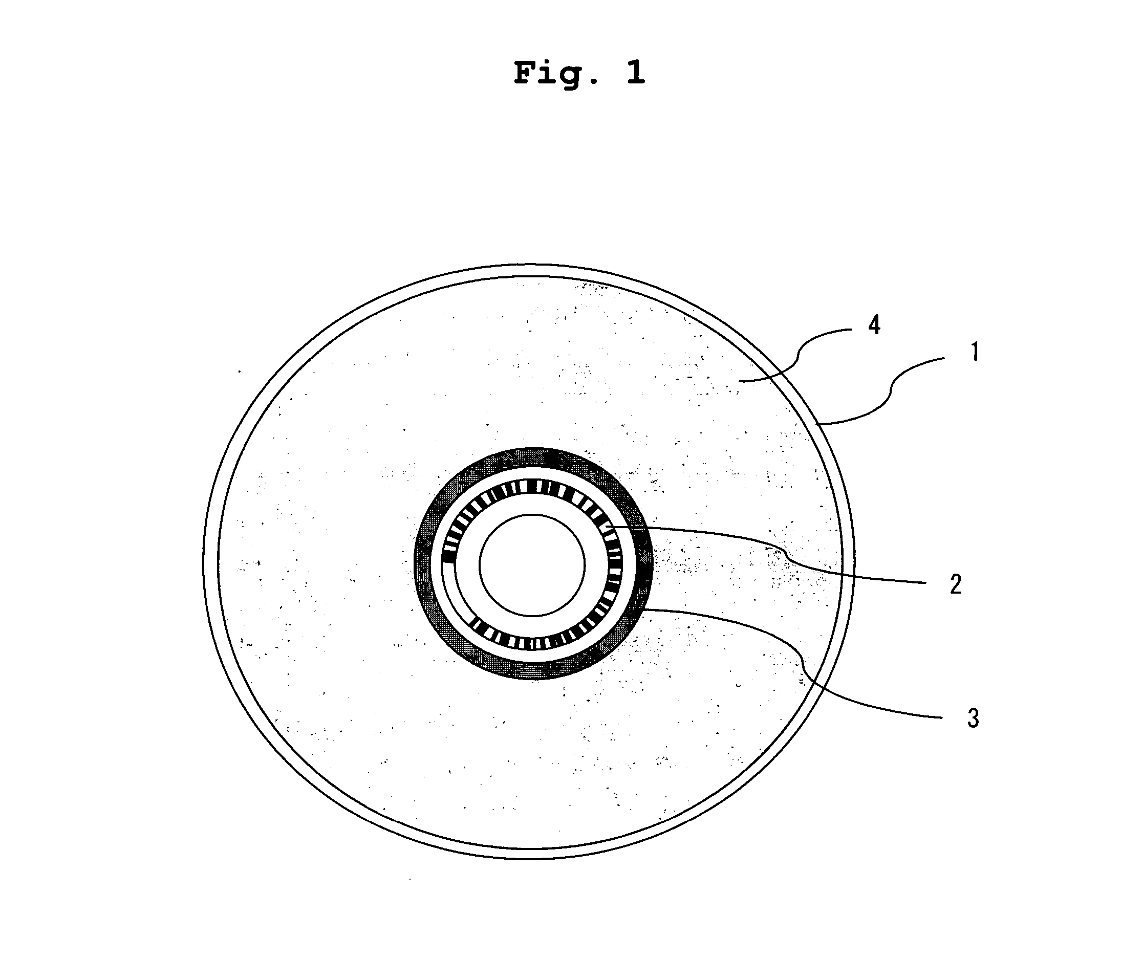
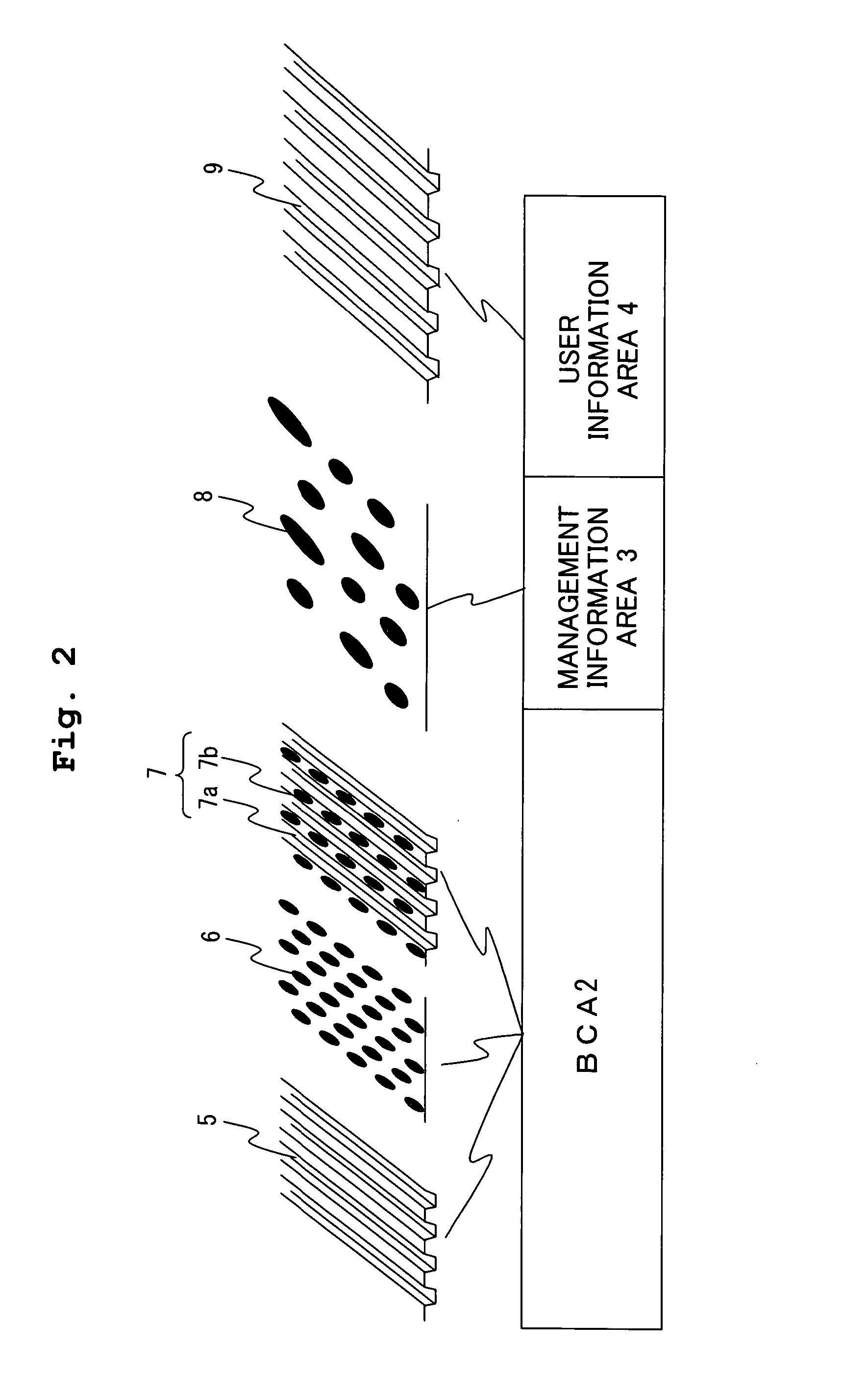
[0078] At first, a stamper, which was manufactured by the production method as described above, was installed to a known injection molding machine to manufacture a substrate 10 by injection-molding a polycarbonate resin of the optical information-recording medium grade. The substrate 10 is made of polycarbonate having a diameter of 120 mm and a thickness of 0.6 mm. As shown in FIG. 1, concave / convex patterns of spiral-shaped grooves and / or pits (emboss pits) are transferred onto one surface of the substrate 10 for BCA, the management information area, and the user information area formed on the glass master disk. In Example 1, BCA was formed in an area having radii of 22.20 mm to 23.20 mm. The straight grooves (not wobbled) having a track pitch of 350 nm, a groove width of 240 nm, and a groove depth of 70 nm were formed in BCA. The management information area was formed in an area having radii of 23.40 mm to 23.80 mm. The pits hav...

example 2

[0098] In Example 2, the concave / convex pattern of BCA was formed with grooves, the track pitch was 370 nm, the groove width was 250 nm, the width between the grooves was 120 nm, and the groove depth was 70 nm. An optical information-recording medium C was manufactured in the same manner as in Example 1 except that the groove dimension of BCA was changed.

example 3

[0099] In Example 3, the concave / convex pattern of BCA was formed with grooves, the track pitch was 370 nm, the groove width was 220 nm, the width between the grooves was 150 nm, and the groove depth was 70 nm. An optical information-recording medium D was manufactured in the same manner as in Example 1 except that the groove dimension of BCA was changed.


PUM

PropertyMeasurementUnit
depthaaaaaaaaaa
depthaaaaaaaaaa
widthaaaaaaaaaa

Abstract

An optical information-recording medium, which is provided with a substrate and a light-absorbing layer formed of a dye material on the substrate, includes a user information area in which a concave / convex pattern including spiral-shaped or concentric grooves are formed, and BCA which is provided on an inner circumferential side of the user information area and in which information is recorded with a bar code, wherein a concave / convex pattern, which is different from the concave / convex pattern in the user information area, is formed in BCA. With this construction, an optical information-recording medium, on which BCA information is reproduced without performing any tracking, is provided, wherein a BCA reproduced signal having a satisfactory signal quality is obtained from BCA.

Description

BACKGROUND OF THE INVENTION [0001] 1. Field of the Invention [0002] The present invention relates to an optical information-recording medium. In particular, the present invention relates to an optical information-recording medium on which management information is recorded with a bar code. [0003] 2. Description of the Related Art [0004] The optical information-recording medium such as DVD-ROM includes a medium having an area which is disposed at the innermost circumference thereof and from which information can be read without performing any tracking servo control. Those known as such an area include BCA (Burst Cutting Area) in which information is recorded with a bar code (see, for example, Japanese Patent Application Laid-open Nos. 10-188361 and 6-203412). In the case of Japanese Patent Application Laid-open No. 10-188361, the management information is recorded in BCA which is disposed outside the user information area, in accordance with a modulation system which is different fro...

Claims


Application Information

Patent Timeline
Patent Type & Authority Applications(United States)
IPC IPC(8): G11B7/24
CPCG11B7/0053G11B7/00736G11B7/24079
Inventor OTA, HIRONORINAGATAKI, YOSHIYUKISUGIYAMA, TOSHINORI
Owner HITACHT MAXELL LTD
Why Eureka
Try Eureka