
Method of configuring system layers for synchronous Ethernet

a technology of ethernet and system layers, applied in the field of synchronous ethernet, can solve the problems of inability to carry time delay-sensitive data such as moving pictures and voice, the existing ethernet layer structure illustrated in fig. 1 has limitations for synchronous ethernet, and the band requesting and allocating procedure has not been developed

Inactive Publication Date: 2006-05-18
SAMSUNG ELECTRONICS CO LTD
View PDF0 Cites 46 Cited by
  • Summary
  • Abstract
  • Description
  • Claims
  • Application Information

AI Technical Summary

Problems solved by technology

As the Ethernet is based on the CSMA / CD protocol which grants the same priority to all Ethernet frames and sends them competitively, the Ethernet is generally not suitable for carrying time delay-sensitive data such as moving pictures and voice.
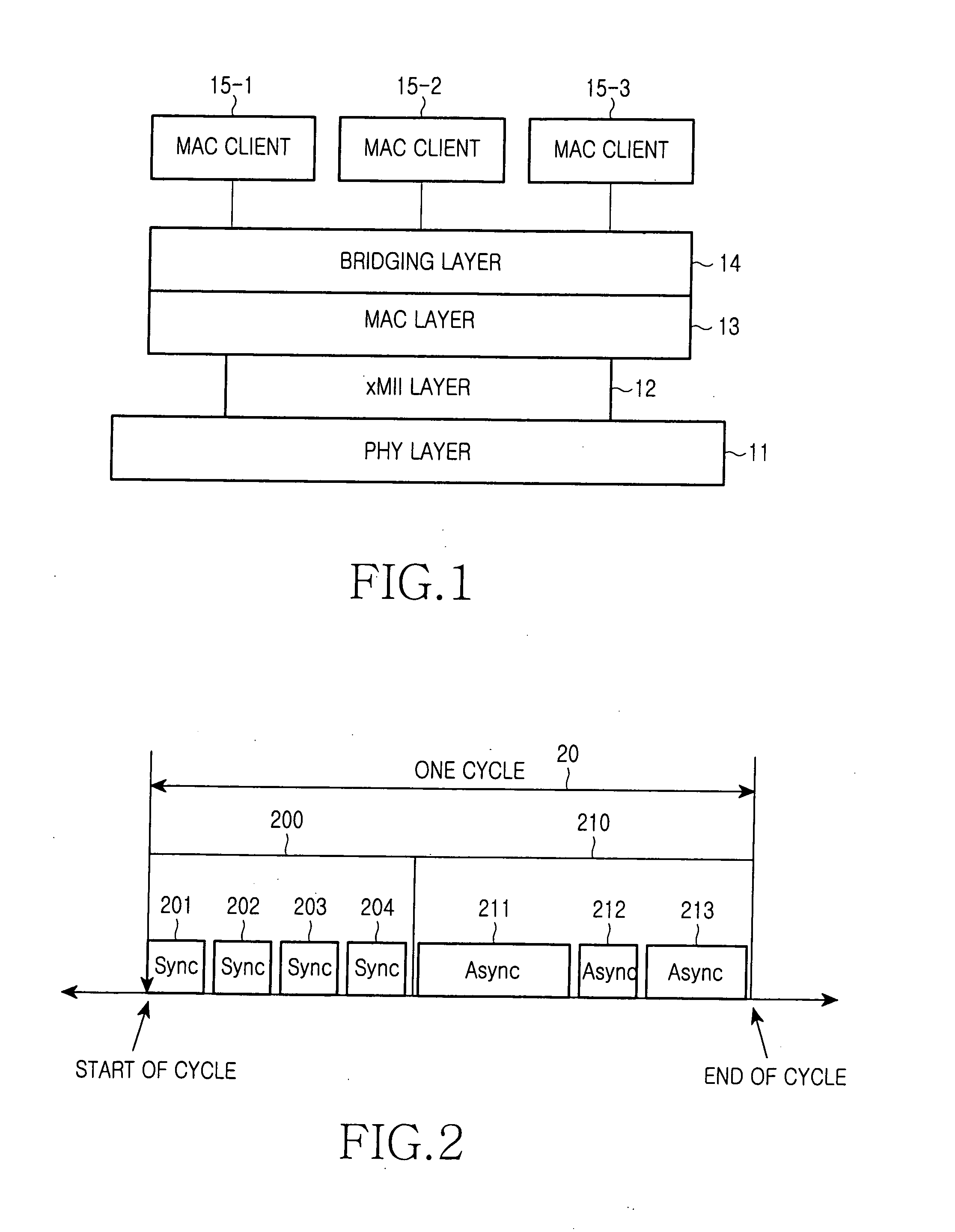
Therefore, the existing Ethernet layer structure illustrated in FIG. 1 has limitations for the synchronous Ethernet.
Nevertheless, such a band requesting and allocating procedure has not been developed.
The bandwidth management, however, increases the size of a jitter buffer.
Consequently, since the requirement for the existing IEEE 802.3p technology is different from the synchronous Ethernet, the layer structure of the former is not viable for the latter.

Method used


Image

  • Method of configuring system layers for synchronous Ethernet
  • Method of configuring system layers for synchronous Ethernet
  • Method of configuring system layers for synchronous Ethernet

Examples


first embodiment

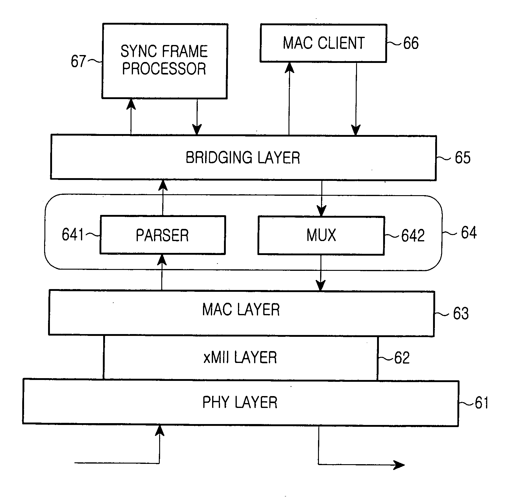
[0051] Compared to the present invention, the parser 641 and the MUX 642 reside above the MAC layer 63, not in the xMII layer 62. In this case, information indicating the start of a super frame and information distinguishing sync sub-packets from async sub-packets are included in an Ethernet Header. Therefore, parsing can be performed based on information resulting from processing in the MAC layer 63. The information indicating the start of a super frame and information distinguishing sync sub-packets from async sub-packets are stored before generation of an Ethernet frame in the MAC layer 63. Information indicating the start of a super frame and information distinguishing sync sub-packets from async sub-packets are set in “TYPE” fields of sync sub-packets packet that form a sync sub-frame.

[0052] Regarding a downlink signal (i.e. a signal from an upper layer to a lower layer) with reference to FIG. 3, upon receipt of multimedia data (i.e. sync packets) supporting an ASI interface su...

second embodiment

[0056] However, in contrast to the second embodiment, information indicating the start of a 125-μs super frame and information distinguishing sync sub-packets from async sub-packets in the super frame are set in Sync Headers. This means that parsing is possible based on information obtained from processing in the MAC layer 63. The information indicating the start of a super frame and information distinguishing sync sub-packets from async sub-packets are stored before generation of an Ethernet frame in the MAC layer 63. This information is set in the Sync Header of a sync sub-frame.

[0057] As described above in the embodiment above, a synchronous Ethernet layer configuration method in which a synchronous Ethernet is implemented using existing PHY and MAC layer devices. This results in a synchronous Ethernet that can transmit multimedia data via existing Ethernet systems.

[0058] In addition, this structure provides compatibility with existing devices in protocol layers, thereby improvi...


PUM


Abstract

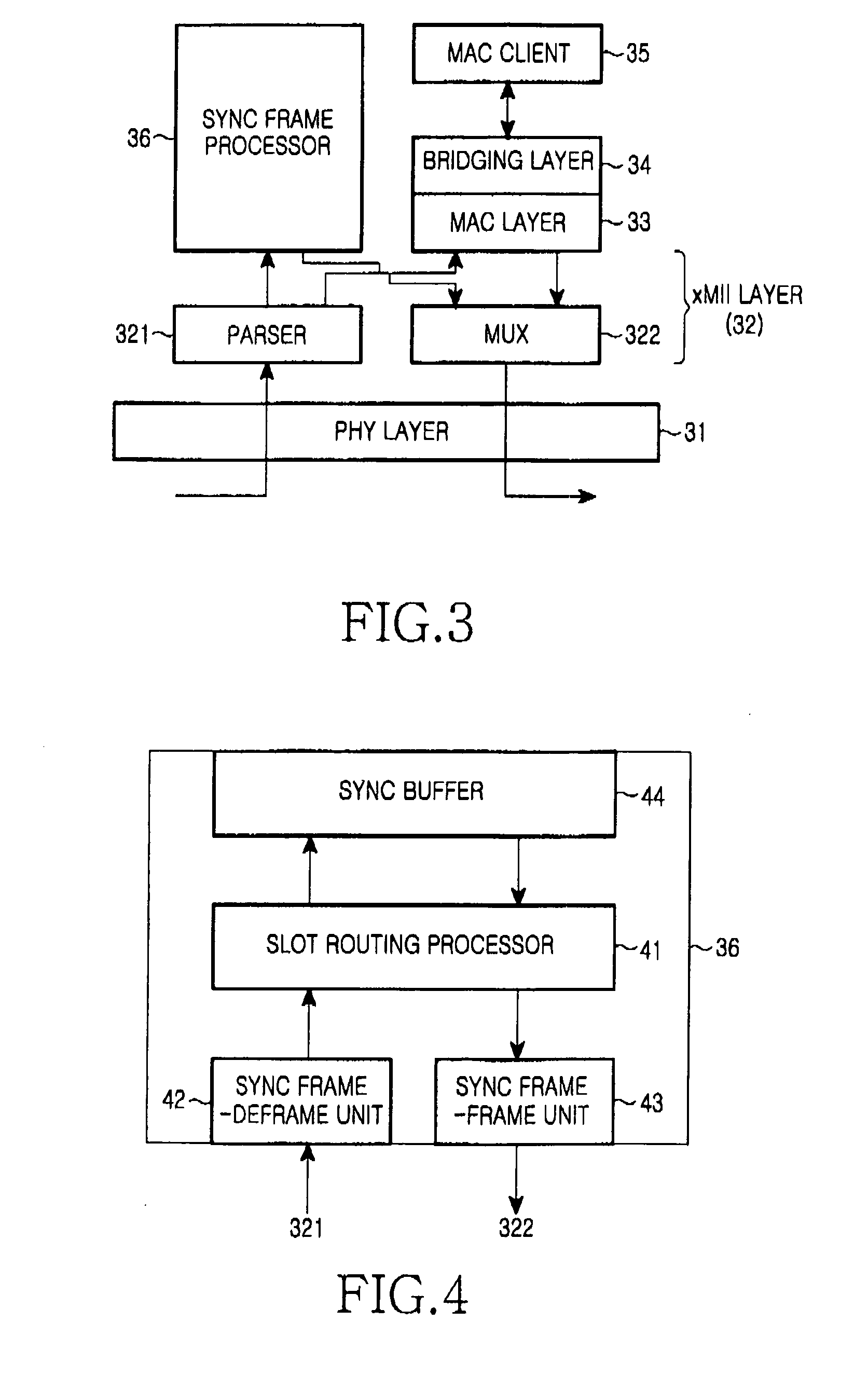
A method of configuring system layers for a synchronous Ethernet is provided. In the method, a physical layer takes charge of input and output of an Ethernet frame in direct relation to hardware, an xMII (x Media Independent Interface) layer connects the physical layer to a data link layer. The data link layer has a sync frame processor for processing a synchronous frame and an async frame processor for processing an asynchronous frame. A parser and multiplexer (MUX), included in the x MII layer, construct a super frame with a synchronous frame and an asynchronous frame, transmit the super frame through the physical layer, parse a received super frame into a synchronous frame and an asynchronous frame, and transmit the synchronous and asynchronous frames to the data link layer.

Description

CLAIM OF PRIORITY [0001] This application claims priority under 35 U.S.C. § 119 to an application entitled “Method of Configuring System Layers for Synchronous Ethernet,” filed in the Korean Intellectual Property Office on Nov. 18, 2004 and assigned Serial No. 2004-94801, and an application entitled “Method of Configuring System Layers for Synchronous Ethernet,” filed in the Korean Intellectual Property Office on Jan. 4, 2005 and assigned Serial No. 2005-628, the contents of both of which are incorporated herein by reference. BACKGROUND OF THE INVENTION [0002] 1. Field of the Invention [0003] The present invention relates generally to a synchronous Ethernet, and in particular, to a method of configuring system layers for a synchronous Ethernet. [0004] 2. Description of the Related Art [0005] Ethernet is the most widespread LAN (Local Access Network) technology in use. The interfaces and protocols of Ethernet have been standardized as IEEE (Institute of Electrical and Electronics Eng...

Claims


Application Information

Patent Timeline
IPC IPC(8): H04L12/413
CPCH04L12/413
Inventor CHO, JAE-HUNKIM, SANG-HOKOH, JUN-HOKIM, JONG-KWONOH, YUN-JEYOON, JONG-HO
Owner SAMSUNG ELECTRONICS CO LTD
Learn More