Directional antenna

a directional antenna and antenna technology, applied in antennas, antenna details, electrical equipment, etc., can solve the problems of unsightly vertical wires protruding from the exterior of the vehicle, limited telecommunication services integrated in the automobile, and easy damage, and achieve the effect of maximizing antenna performan

Inactive Publication Date: 2006-05-18
DELPHI TECH INC
View PDF4 Cites 0 Cited by
  • Summary
  • Abstract
  • Description
  • Claims
  • Application Information

AI Technical Summary

Benefits of technology

[0011] Features of the invention are achieved in part by making use of an existing light as the radiating antenna element. Together, the light filament and the light beam reflector direct the RF transmission toward an intended receiver. In an embodiment, the directional antenna system includes an alternating current (AC) source, and an illuminator having a reflective surface for directing a beam of light. The AC source provides AC via a transmission link to the illuminator for creating a magnetic field about the illuminator and radiating electromagnetic radio waves. The reflective surface directs the electromagnetic radio waves in a predetermined direction, maximizing antenna performance. In an embodiment, the illuminator is a filament incorporated into a vehicle headlight wherein a direct current (DC) source supplies current to the filament. The antenna system may be incorporated with a fixed structure or with a mobile vehicle including a car, truck, airplane, ship, boat, etc.

Problems solved by technology

In the past, telecommunication services integrated in an automobile were limited to a few systems, mainly analog radio reception (AM / FM bands), for which a simple whip antenna was mounted to and extended from a vehicle body.
A disadvantage of this fixed mast monopole antenna is that it protrudes from the exterior of the vehicle as an unsightly vertical wire with a height of roughly one quarter wavelength of the signal frequency.
A further disadvantage of the monopole antenna is that it is susceptible to damage due to vandalism and car wash systems.
Another disadvantage of the monopole antenna is that it is typically narrowband with a bandwidth of roughly ten percent.
However, since vehicle design is often dictated by styling, the presence of numerous protruding antennas is not desirable.
However, rear window antennas exhibit troubles, for example pattern disconnection of the thin window antenna often occur.
In a number of applications, an omnidirectional antenna is less effective in achieving optimum values for these characteristics, as compared with a directional antenna.
However, directional antennas currently suffer from disadvantages of having complex shapes and large size, making them difficult to package in a vehicle.
However, the sheet metal shields and adversely affects the performance of the directional antenna.

Method used


Image

  • Directional antenna
  • Directional antenna
  • Directional antenna

Examples


Embodiment Construction

[0023] Exemplary embodiments are described with reference to specific configurations. Those of ordinary skill in the art will appreciate that various changes and modifications can be made while remaining within the scope of the appended claims. Additionally, well-known elements, devices, components, methods, process steps and the like may not be set forth in detail in order to avoid obscuring the invention. Further, unless indicated to the contrary, the numerical values set forth in the following specification and claims are approximations that may vary depending upon the desired antenna characteristics sought to be obtained by the present invention.

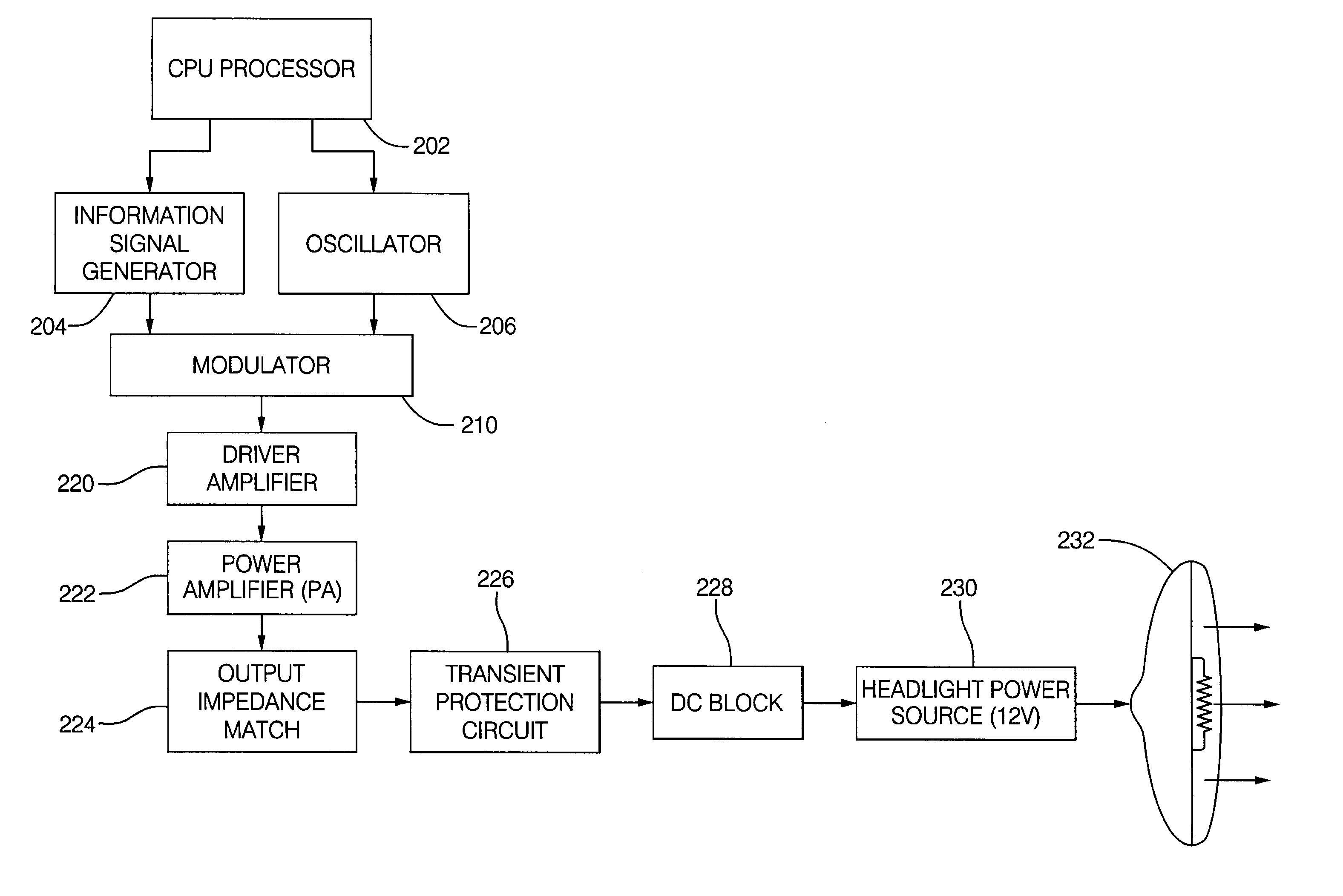
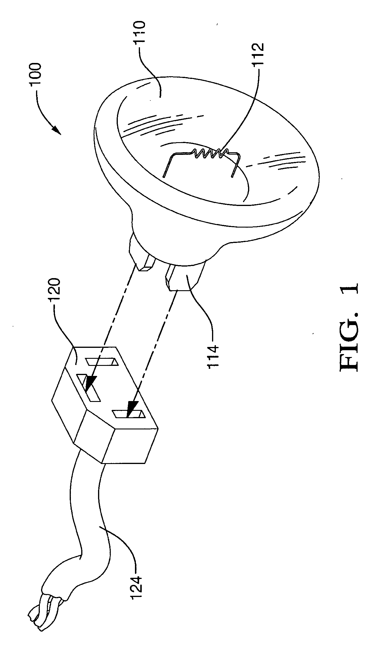
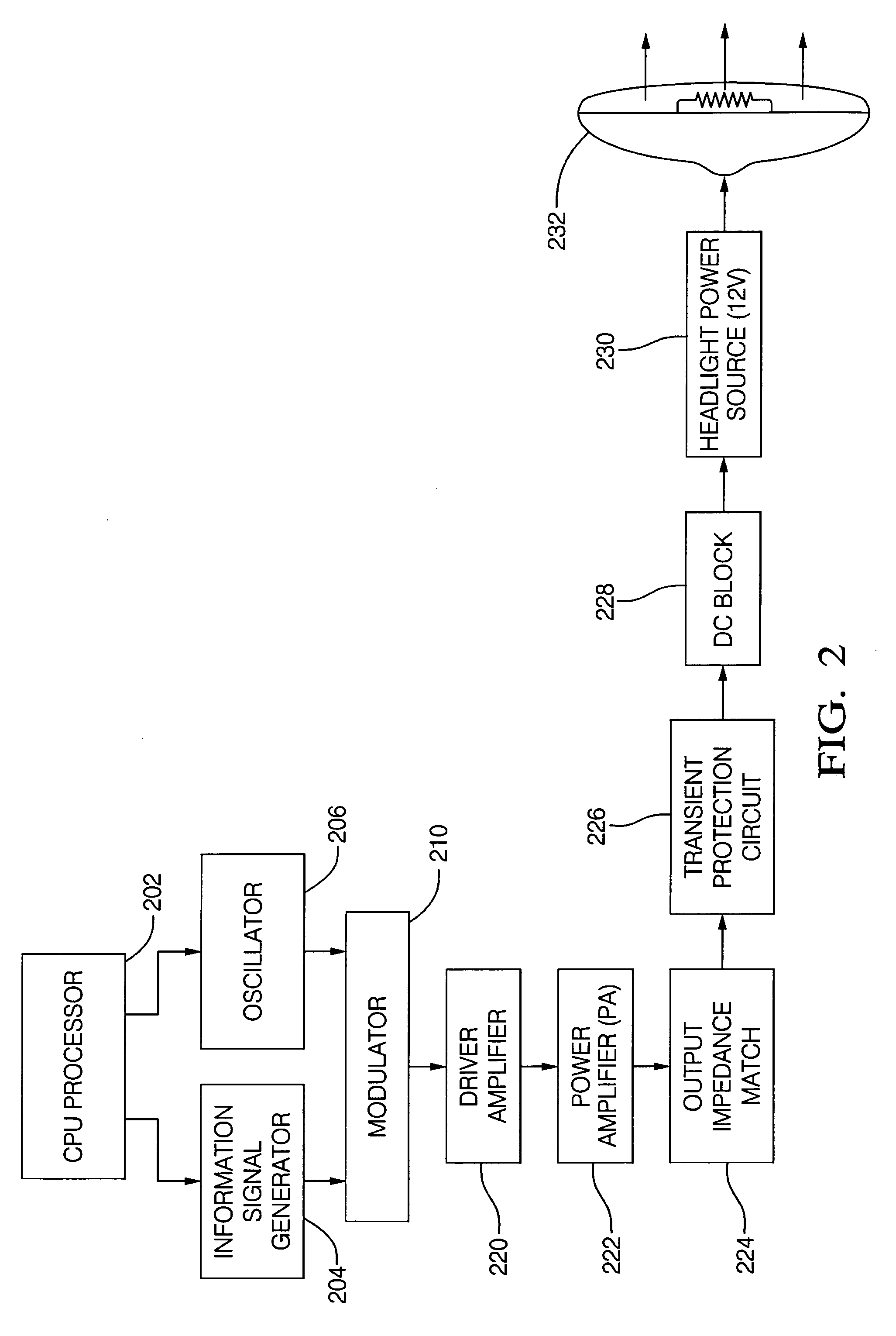
[0024] A system and method is described herein for providing a directional antenna by transmitting an information signal to a light source having a beam directing reflective surface. It is to be appreciated that features of the discussion and claims may be utilized with a simple light, which may be situated to a fixed structure such as ...


PUM


Abstract

A directional antenna is provided that transmits an information signal to a light source having a beam directing reflective surface. In an aspect, the information signal is impressed across a light filament and the reflective surface directs the electromagnetic radio waves in a predetermined direction. The radiated information signal may be used to detect an object or communicate with a receiver. The light source can be attached to a fixed structure or to mobile vehicle. In the case of a mobile vehicle, the antenna is fully concealed and can operate with an unmodified, factory installed vehicle headlight. In an aspect, material costs, manufacturing costs and assembly costs are reduced as compared to presently available antennas.

Description

FIELD OF THE INVENTION [0001] The invention relates generally to wireless communications, and more particularly to a combined transmitter and receiver incorporating a light source having a beam directing reflective surface for use as a directional antenna. BACKGROUND OF THE INVENTION [0002] In the past, telecommunication services integrated in an automobile were limited to a few systems, mainly analog radio reception (AM / FM bands), for which a simple whip antenna was mounted to and extended from a vehicle body. A disadvantage of this fixed mast monopole antenna is that it protrudes from the exterior of the vehicle as an unsightly vertical wire with a height of roughly one quarter wavelength of the signal frequency. This is because the whip antenna must exhibit certain mechanical characteristics to achieve user needs and meet required electrical performance. The antenna length, or the length of each element of an antenna array, depends on the received and transmitted signal frequenci...

Claims


Application Information

Patent Timeline
Patent Type & Authority Applications(United States)
IPC IPC(8): H04B10/00
CPCH01Q1/06H01Q1/3291
Inventor CAPPS, CHARLES P.KOHLER, JAMES L.
Owner DELPHI TECH INC
Why Eureka
Try Eureka