Tool and accessory connecting system

a connecting system and tool technology, applied in boring/drilling machines, drilling pipes, boring/drilling machines, etc., can solve the problems of affecting the operation of the tool, and requiring moving parts for the tool holder, so as to prevent the carrying system

Inactive Publication Date: 2006-05-18
MILWAUKEE ELECTRIC TOOL CORP
View PDF34 Cites 75 Cited by
  • Summary
  • Abstract
  • Description
  • Claims
  • Application Information

AI Technical Summary

Benefits of technology

[0016] In some aspects, the carrying system of the present invention permits the operator to connect a power tool to the belt clip for various periods of time while conveniently maintaining the power tool within reach. The connectors, such as the stud and the receptacle, are relatively small and non-obtrusive, preventing the carrying system from getting in the way of the operator. In one construction, the receptacle may be incorporated into the body of the tool. Preferably, the receptacle does not protrude from the tool to help prevent the tool from catching on objects or clothing.

Problems solved by technology

Also, the holster (with and without the tool) is unwieldy and burdensome and get in the way of the operator.
Some existing tool holders require moving parts and may be relatively heavy.
Also, the cradling devices project from an operator's work belt and may get in the way and hinder movement of the operator.
With some existing holding devices formed on the tool, the projections are an impediment and may catch on loose clothing or objects around the work site.
Also, the projections may be inconvenient for the operator to use.
Some existing devices cannot be used to connect accessories to the tool.

Method used


Image

  • Tool and accessory connecting system
  • Tool and accessory connecting system
  • Tool and accessory connecting system

Examples


Embodiment Construction

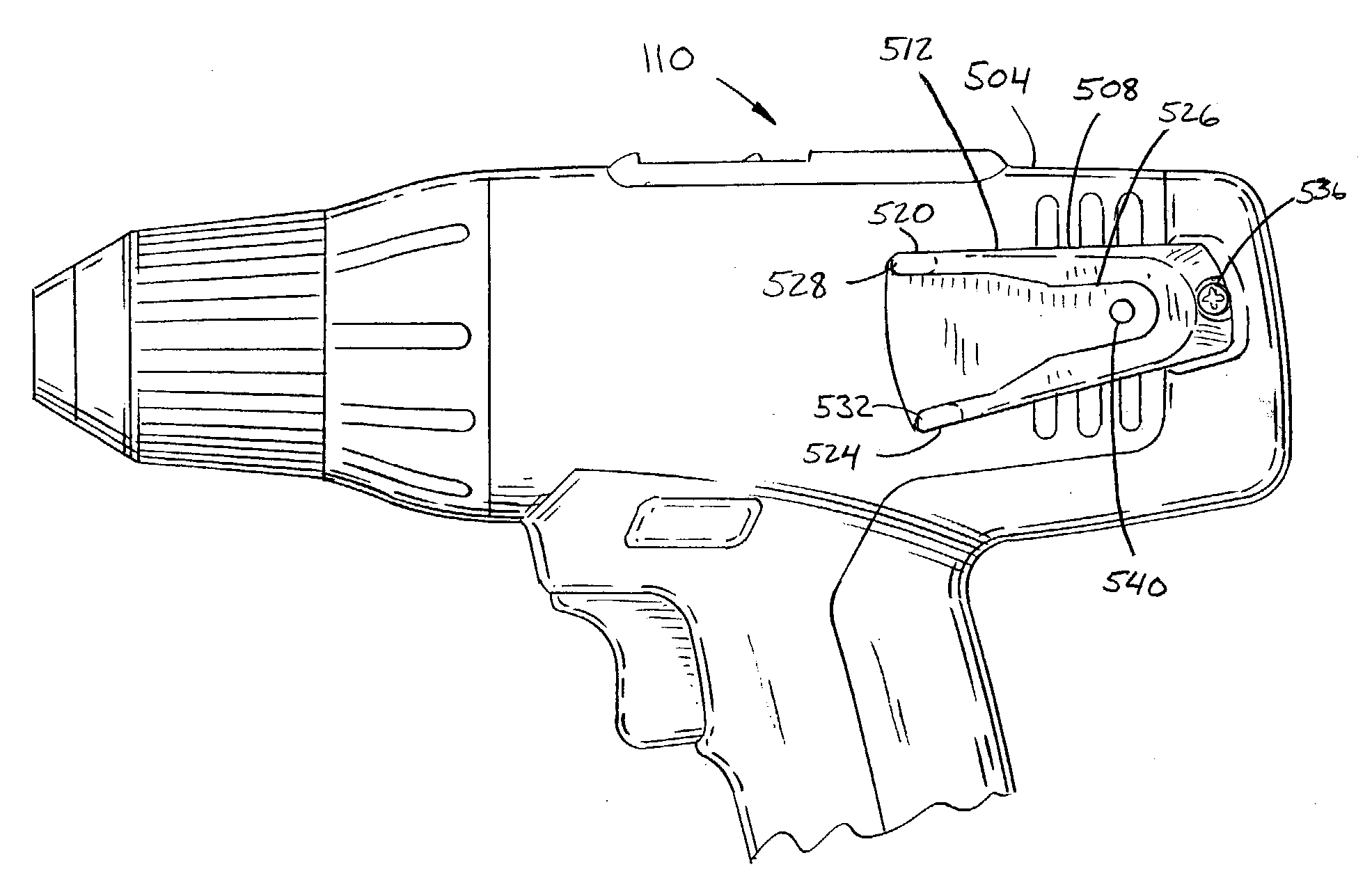
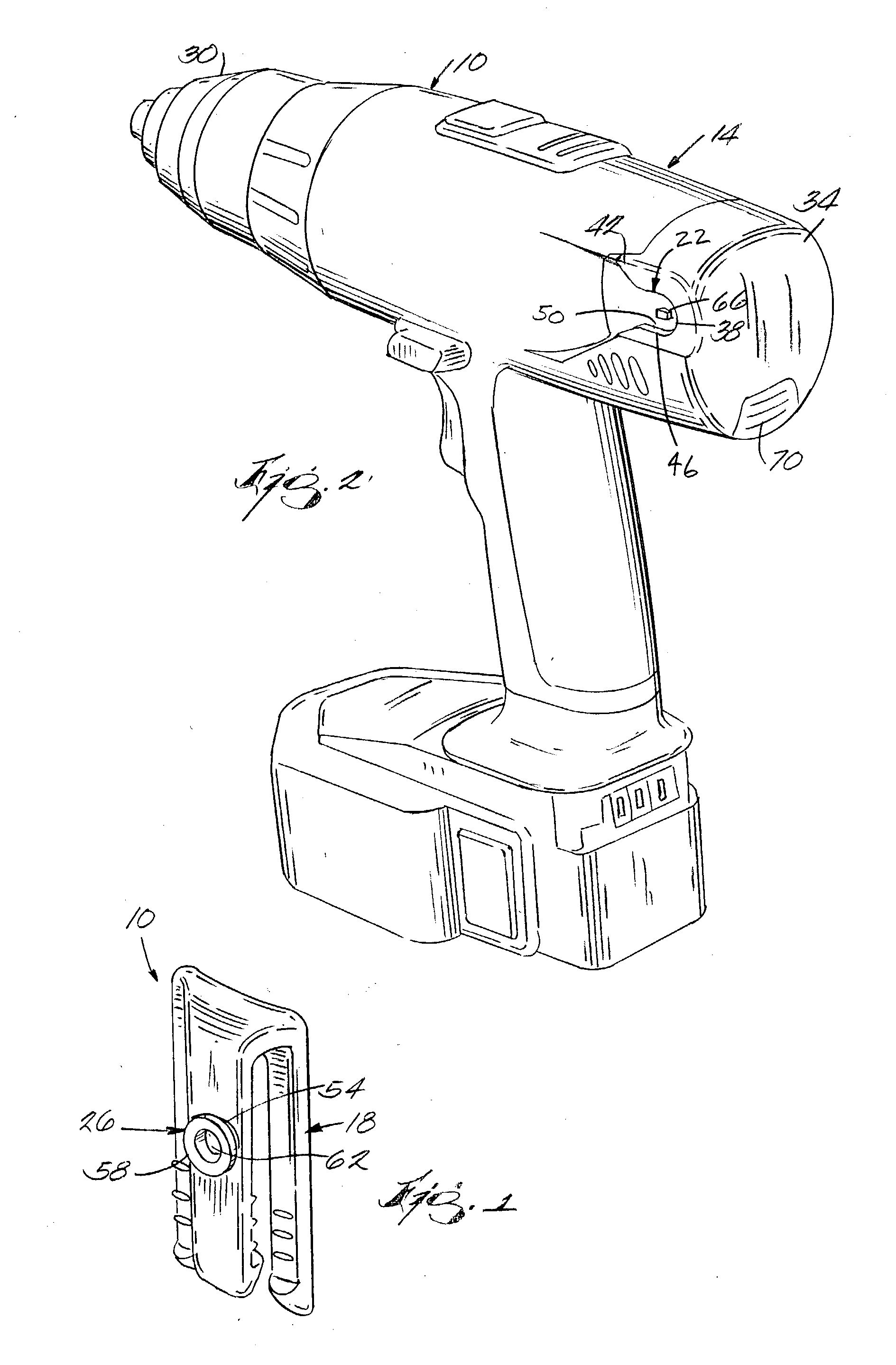
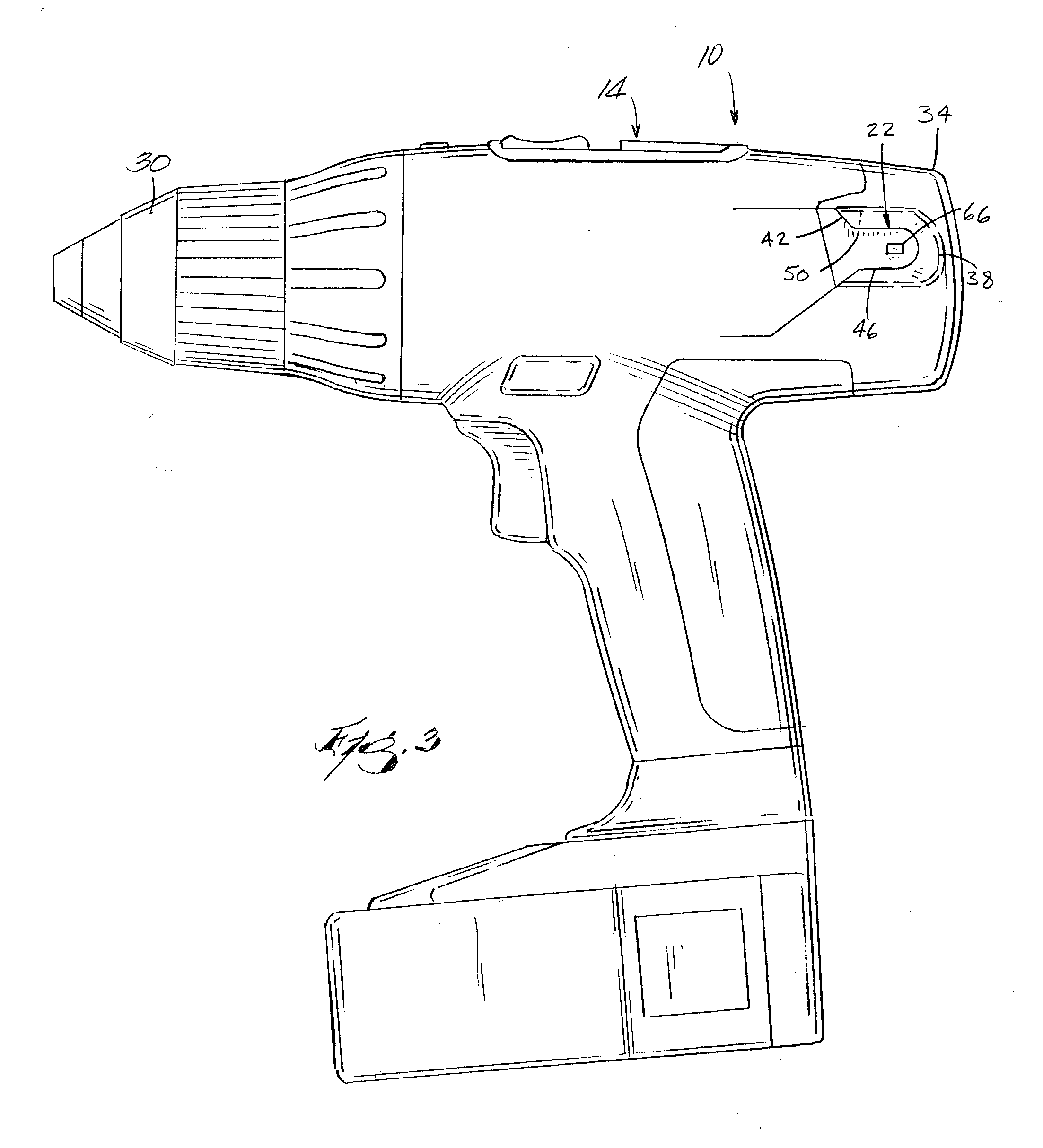
[0115]FIGS. 1 and 2 illustrate a carrying system 10 for a power tool 14. The carrying system 10 may be used to interconnect the power tool 14 to a component. In the illustrated construction, the component includes a belt clip 18, and the power tool 14 may be connected to the belt clip 18 for hands free support and retention of the power tool 14 on the belt clip 18. The carrying system 10 includes cooperating connectors, such as, in the illustrated construction, a receptacle 22 and a stud 26, which are detachably interconnected with each other. In the illustrated construction, the receptacle 22 is incorporated into the body of the power tool 14, and the stud 26 is incorporated into the belt clip 18.

[0116] The power tool 14 includes a forward portion 30 and a rearward portion 34. In the illustrated construction, the power tool 14 includes a drill, and a tool holder or chuck is disposed near the forward portion 30. In the illustrated construction, the receptacle 22 includes a recessed...


PUM

PropertyMeasurementUnit
elasticaaaaaaaaaa
widthaaaaaaaaaa
slot widthaaaaaaaaaa

Abstract

Carrying systems, connecting systems and methods. The system connects a power tool and a component. In some constructions and in some aspects, the power tool includes a housing and a U-shaped receptacle defined by the housing. In some constructions and in some aspects, the component includes a stud selectively engageable with the receptacle to connect the power tool and the component. A locking mechanism is positioned within the receptacle and includes a cam. The locking mechanism is engageable with the stud to restrict movement of the stud with respect to the receptacle. The stud includes a recess at an end of the stud. The cam is selectively engageable with the recess to retain the stud within the receptacle. The cam is movable between a lock position and a released position. In the locked position, the cam extends into the recess and engages the stud. In the released position, the cam is retracted from the recess and is disengaged with the stud.

Description

RELATED APPLICATIONS [0001] The present application claims the benefit of prior-filed co-pending provisional patent application Ser. No. 60 / 364,693, filed Mar. 15, 2002.FIELD OF THE INVENTION [0002] This invention relates to power tools and power tool accessories and, more particularly, to a connecting system for power tools and accessories. BACKGROUND OF THE INVENTION [0003] Power tools are used to for various operations including sawing and drilling. In between or during such operations, the operator may want to carry the tool “hands-free”, or to store the tool temporarily so that other operations can be performed with both hands. SUMMARY OF THE INVENTION [0004] Some tool holsters are relatively large to accommodate the tool. Also, the holster (with and without the tool) is unwieldy and burdensome and get in the way of the operator. [0005] Some existing tool holders require moving parts and may be relatively heavy. Also, the cradling devices project from an operator's work belt an...

Claims


Application Information

Patent Timeline
Patent Type & Authority Applications(United States)
IPC IPC(8): B23B39/00A45F5/00E21B17/22H02J7/00B25F5/02B25H3/00
CPCB25F5/021Y10T408/96B25H3/006B25F5/029
Inventor ZEILER, JEFFREY M.JAMES, THOMAS P.STEGEHUIS, PAMELA S.HEMPE, DAVID A.YANKE, BURTON E.
Owner MILWAUKEE ELECTRIC TOOL CORP
Why Eureka
Try Eureka