Remote autonomous intelligent air flow control system and network

a technology of intelligent air flow and control system, applied in ventilation systems, lighting and heating apparatus, heating types, etc., to achieve the effect of increasing local flow

Inactive Publication Date: 2006-05-18
ARONSTAM PETER S
View PDF22 Cites 149 Cited by
  • Summary
  • Abstract
  • Description
  • Claims
  • Application Information

AI Technical Summary

Benefits of technology

[0011] An advantage of the present invention is that the individual flow control devices through out the ductwork can communicate with each other providing a collective intelligence enabling of managing the interdependence of air flow on each other.
[0012] It is a further object of the present invention to enable the flow control devices to determine the best independent behavior to satisfy the overall environmental control goals.
[0013] It is a further object of the present invention to eliminate the need for a central controller or central processing unit to achieve overall environmental control goals. An advantage of this configuration is that even if one or more flow control devices fail, the remaining collective of devices adapt and continue to operate towards the overall environmental control goals. Further, if the communications means between flow control devices partially or totally fail, the flow control devices still continue to operate independently, or partially independently, towards achieving the overall environmental control goals. Thus, there is no central processing unit to cause complete system failure.
[0014] It is a further object of the present invention to have the ability to increase the local flow by either boosting flow or influencing other flow control devices in the ductwork to restrict flow.
[0015] It is a further object of the present invention to enable a flow control device to automatically adjust, regulating an area to a desired temperature.
[0016] It is a further object of the present invention to enable installation of one or more flow control devices without the need for electrical wiring, modification of the duct work or register boxes, or connecting to the environmental control unit.

Problems solved by technology

Further, if the communications means between flow control devices partially or totally fail, the flow control devices still continue to operate independently, or partially independently, towards achieving the overall environmental control goals.

Method used


Image

  • Remote autonomous intelligent air flow control system and network
  • Remote autonomous intelligent air flow control system and network
  • Remote autonomous intelligent air flow control system and network

Examples


adaptive embodiment

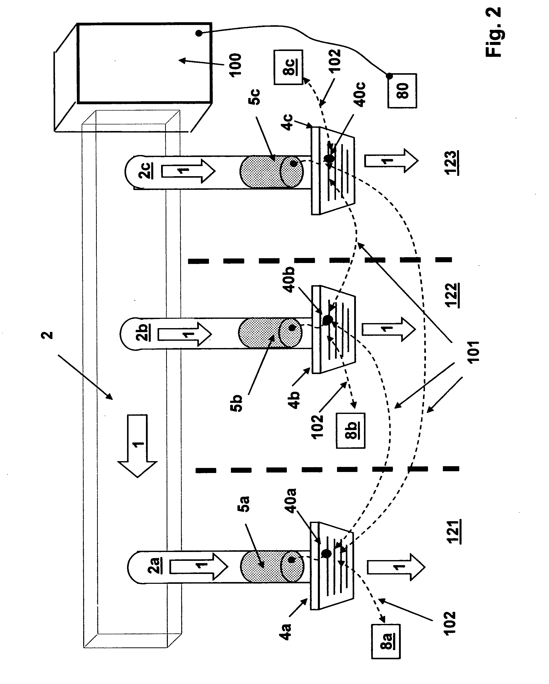
[0077] A greater measure of improvement of the performance of the flow control devices can be implemented by adding adaptive control means. If adaptive means are turned on, step S13, the program instructions are allowed to repeat. At appropriate intervals, step S14, microcontroller 50 of flow control device 5a repeats the above described sequence, steps S4 to S13. The intervals between repetitions may be governed by several means, including changes in environmental status table 102, operational status table 101, timed interval, delay interval, and updated operational status tables from other flow control devices. Microcontroller 50 requests, by way of communications device 40, environmental status table 102 from sensor 8a. Microcontroller 50 sends operational status table 101a to flow control devices 5b and 5c by way of communications driver 41 and communications device 40. Microcontroller 50 updates operational status table 101a, containing data reflecting the environmental conditi...

table embodiment

OPERATIONAL STATUS TABLE EMBODIMENT

[0083] Operational control table 101 includes the parameters necessary to execute the previously described embodiments, such as temperature, requested temperature, and flow restriction device temperature. Operational control table 101 also includes parameters which enable more advanced adaptive program instructions. For example, by tracking whether a given room reaches its goal during an on state cycle of the environmental control unit, the parameters associated with the inverse linear relationship between the difference between the actual temperature and the requested temperature (delta T) and the amount of flow restriction can be adjusted.

[0084] In another example, in order to protect the environmental control unit from damage due to excessive restriction of flow, the duct air pressure upstream of the flow control device may be calculated knowing the temperature and the rotation rate of the rotating structure, as deduced from the potential volta...


PUM


Abstract

The present invention provides one or more autonomous in-duct or register grill mounted flow control devices, each of which has the capability to restrict or boost air flow through the duct or vent to which it is attached. The individual flow control devices may be in communication with other flow control devices in the duct works, having an ability to adapt in a cooperative fashion to optimize the environment served by the ductwork. In a preferred embodiment, each of the flow control devices provides its own power and does not require changing the existing ductwork or register boxes for installation.

Description

FIELD OF THE INVENTION [0001] The present invention relates generally to the control of fluid movement through a duct or conduit. More particularly, the present invention relates to the use of one or more autonomous flow control devices, able to operate independently of an existing environmental control system. BACKGROUND OF THE INVENTION [0002] The typical air vents in commercial and residential settings consist of louvers which may be manually opened or closed in varying degrees. These air vents provide a limited ability to adjust the amount of air flow into a room or area, the air coming from a central environmental control unit, such as a furnace, central air conditioner, or dehumidifier. There may be several such vents connected, via ducts, to the central environmental control unit, each vent providing air flow to a room or area. Since these vents are generally connected to a central unit, the opening or closing of one or more vents affects the air flow to the other vents. If i...

Claims


Application Information

Patent Timeline
Patent Type & Authority Applications(United States)
IPC IPC(8): F24F11/00
CPCF24F11/0001F24F11/006F24F11/30F24F11/62F24F11/74
Inventor ARONSTAM, PETER S.KNOBLOCH, CHARLES SARON
Owner ARONSTAM PETER S
Why Eureka
Try Eureka