Leadscrew set for stepping motor

Inactive Publication Date: 2006-05-25
TRICORE CORP
View PDF4 Cites 5 Cited by
  • Summary
  • Abstract
  • Description
  • Claims
  • Application Information

AI Technical Summary

Benefits of technology

[0005] The present invention has been accomplished under the circumstances in view. It is therefore the main object of the present invention to provide a leadscrew set, which provided a better assembly between the leadscrew and magnet part, and the magnet part can be assembled on th

Problems solved by technology

A conventional leadscrew set for stepping motor, the leadscrew set comprises a magnet part which is difficult to assemble on a leadscrew, and the gluing effect cannot have a good connection between the ma

Method used


Image

  • Leadscrew set for stepping motor
  • Leadscrew set for stepping motor
  • Leadscrew set for stepping motor

Examples


Embodiment Construction

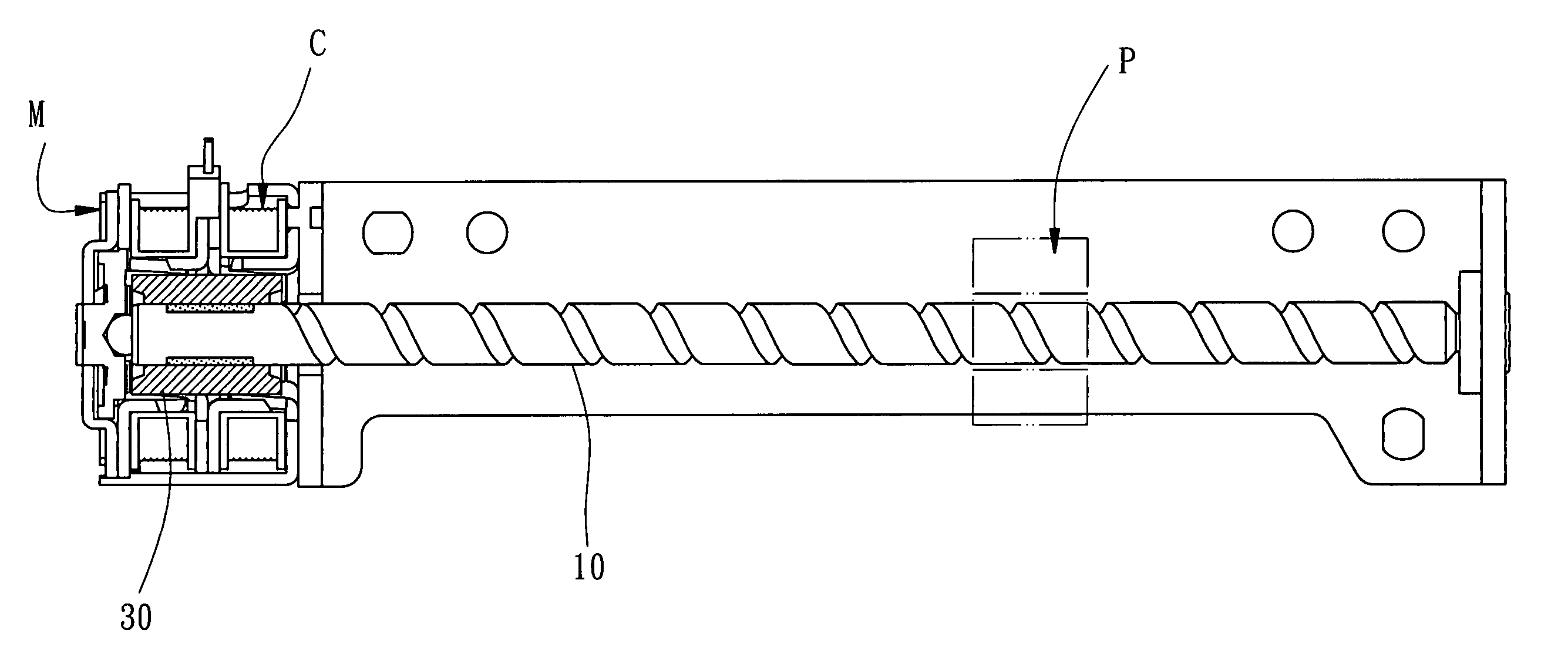
[0016] Referring to FIG. 1, a leadscrew set in accordance with the present invention adapted to assemble on a motor M which comprises a coil bobbin C, and provided for driving a movement set P moving forwards and backwards.

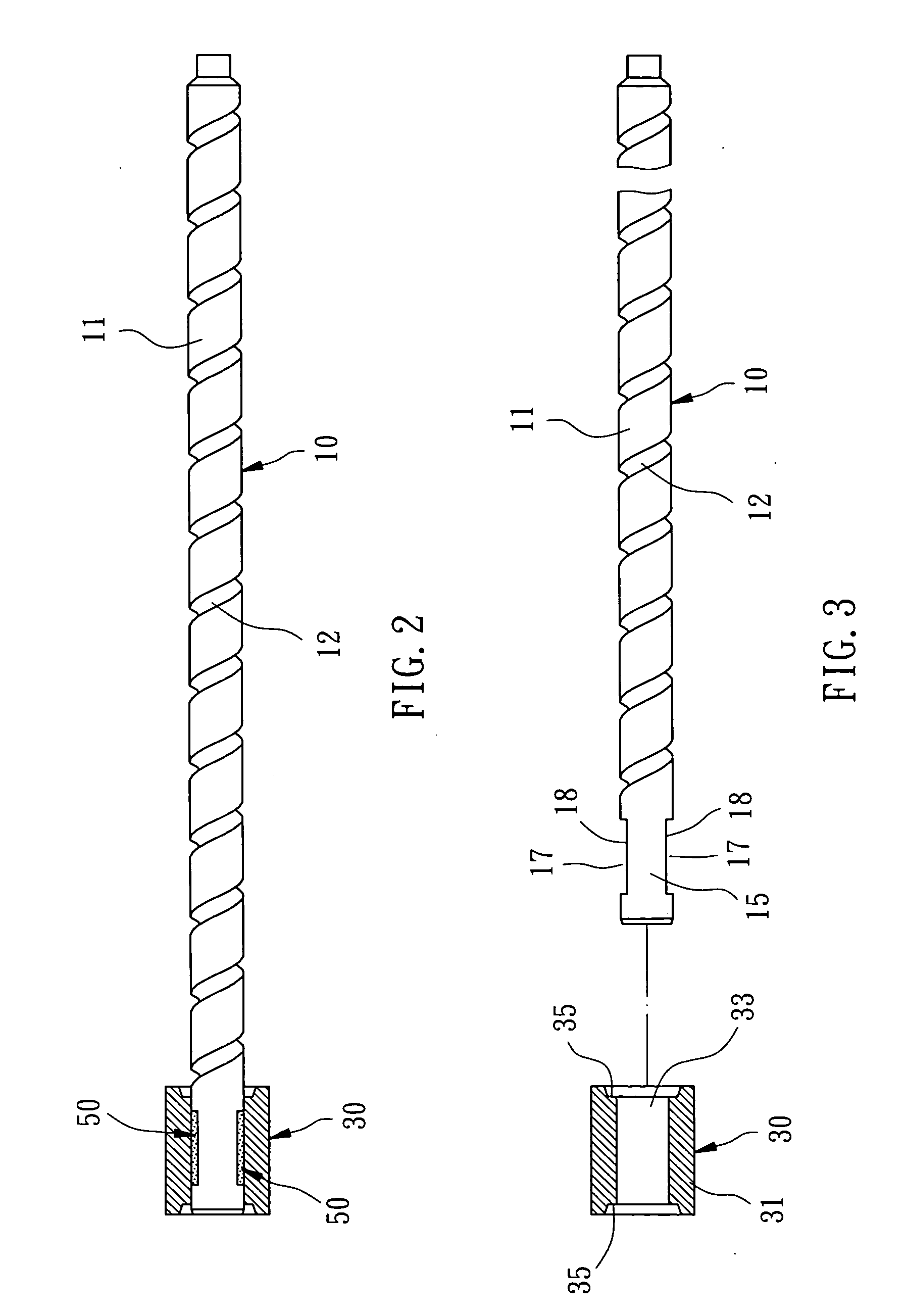
[0017] Referring to FIGS. 2 and 3, the leadscrew set comprises:

[0018] A leadscrew 10, which has a shaft body 11, a screw portion 12 formed on periphery of the shaft body 11, a magnet connecting portion 15 connected on an end of the shaft body 11, two gluing portions 17 formed of concave shape on the magnet connecting portion 15, each gluing portion 17 has a gluing surface 18.

[0019] A magnet part 30, which has a barrel body 31, a leadscrew fitting hole 33 formed inside the barrel body 31 and positioned at inward of the coil bobbin C and the magnet connecting portion 15 of the leadscrew 10, and two insert guiding holes 35 formed at the two each side opening of the leadscrew fitting hole 33.

[0020] A glue member 50, which glued between the gluing portions 17 of th...


PUM


Abstract

A leadscrew set is installed on a stepping motor which comprises a coil bobbin, the leadscrew set includes a leadscrew, which has a shaft body, a screw portion formed on periphery of the shaft body, a magnet connecting portion connected on an end of the shaft body, two gluing portions formed concave on the magnet connecting portion, each gluing portion has a gluing surface; a magnet part, which has a barrel body, a leadscrew fitting hole formed inside the barrel body and positioned at inward of the coil bobbin and the magnet connecting portion of the leadscrew; and a glue member, which glued between the gluing portions of the leadscrew and the leadscrew fitting hole of the magnet part.

Description

BACKGROUND OF THE INVENTION [0001] 1. Field of the Invention [0002] The present invention relates to motors and more specifically, to a leadscrew set for stepping motor. [0003] 2. Description of the Related Art [0004] A conventional leadscrew set for stepping motor, the leadscrew set comprises a magnet part which is difficult to assemble on a leadscrew, and the gluing effect cannot have a good connection between the magnet part and leadscrew. Moreover, there is not easy to make or waste more time and cost, and the structure of magnet part connected to the leadscrew causing poor magnetic effect, hence have to improvement. SUMMARY OF THE INVENTION [0005] The present invention has been accomplished under the circumstances in view. It is therefore the main object of the present invention to provide a leadscrew set, which provided a better assembly between the leadscrew and magnet part, and the magnet part can be assembled on the leadscrew easily and firmly. It is another object of the p...

Claims


Application Information

Patent Timeline
IPC IPC(8): F16H27/02H02K5/00H02K7/06H02K37/00
CPCY10T74/18576H02K7/06
Inventor HUANG, DAVID
Owner TRICORE CORP
Why Eureka
Try Eureka