
Facing tooth stepped type magnetofluid sealing device

A ferrofluid sealing and stepped technology, which is applied to the sealing of the engine, engine components, mechanical equipment, etc., can solve the problems of poor magnetic concentration effect and pressure resistance, inability to effectively improve the magnetic concentration effect, and inability to effectively resist centrifugal force. , to achieve the effect of improving self-repair ability, reducing loss, and expanding the safe working range

Pending Publication Date: 2019-05-21
GUANGXI UNIVERSITY OF TECHNOLOGY
View PDF2 Cites 1 Cited by
  • Summary
  • Abstract
  • Description
  • Claims
  • Application Information

AI Technical Summary

Problems solved by technology

[0002] In the case of magnetic fluid seals for large-gap rotating shafts, the single-side pole tooth arrangement used in the seal structure results in poor magnetic concentration and pressure resistance; on the other hand, the magnetic fluid seal is prone to failure under high-speed centrifugal force, causing increased The pressure resistance performance of large-gap ferrohydrodynamic seals is one of the hot issues in current research
[0003] For the sealing device described in reference document 1 (the patent publication number is CN207333722U) and the sealing device described in reference document 2 (the patent publication number is CN207569209U), although document one can satisfy the sealing pressure resistance capability to a certain extent, but It cannot effectively resist the centrifugal force generated during high-speed rotation, which will cause serious loss of magnetic fluid and greatly reduce the sealing performance
The structure of the comparative document 2 is a stepped shaft and a stepped pole piece, but it cannot effectively improve the magnetic concentration effect

Method used


Image

  • Facing tooth stepped type magnetofluid sealing device

Examples


Embodiment Construction

[0029] The present invention will be further described below in conjunction with accompanying drawing.

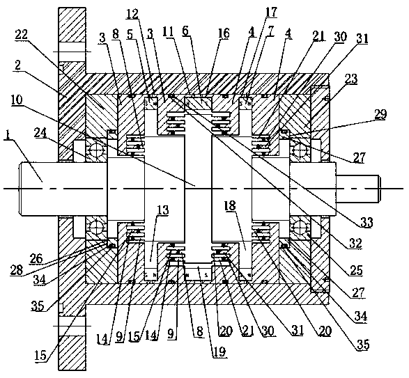
[0030] Such as figure 1 As shown, the split-tooth stepped ferrofluid seal device includes a stepped shaft 1, a housing 2, a left pole shoe ring 3, a right pole shoe ring 4, a left permanent magnet ring 5, a middle permanent magnet ring 6, a right permanent magnet ring 7;

[0031] The stepped shaft 1 includes the primary shaft 10 with the largest diameter and more than two groups of secondary shafts with successively decreasing diameters. The middle radial cross-section of the stage shaft 10 is left-right symmetrical;

[0032]The left pole shoe ring 3 and the right pole shoe ring 4 are sequentially set on the inner wall of the shell 2;

[0033] The left pole shoe ring 3 is set corresponding to the secondary shaft on the left side of the primary shaft 10, and each left secondary shaft corresponds to one; the right end surface of the rightmost left pole shoe ring 3 correspo...


PUM


Abstract

The invention aims at providing a facing tooth stepped type magnetofluid sealing device. The facing tooth stepped type magnetofluid sealing device comprises a stepped shaft, a shell, a left pole shoering, a right pole shoe ring, a left permanent magnet ring, a middle permanent magnet ring and a right permanent magnet ring. The stepped shaft comprises a first-level shaft with the largest diameter,and two more or sets of secondary first-level shafts with the diameters gradually reduced. The secondary first-level shafts are sequentially arranged to the two sides along the side face of the first-level shaft and are symmetric about the middle radial section of the first-level shaft left and right. The magnetism gathering effect can be improved, thus, the magnetofluid sealing pressure endurance capacity is improved, meanwhile, magnetofluid sealing failure caused by the centrifugal force effect can be effectively avoided, losses of magnetofluid are reduced, the reliability of sealing is improved, and the service life of sealing is prolonged.

Description

technical field [0001] The invention belongs to the field of mechanical engineering seals, in particular to a split-tooth stepped magnetic fluid seal device. Background technique [0002] In the case of magnetic fluid seals for large-gap rotating shafts, the single-side pole tooth arrangement used in the seal structure results in poor magnetic concentration and pressure resistance; on the other hand, the magnetic fluid seal is prone to failure under high-speed centrifugal force, causing increased The pressure resistance performance of large-gap ferrohydrodynamic seals is one of the hot issues in current research. [0003] For the sealing device described in reference document 1 (the patent publication number is CN207333722U) and the sealing device described in reference document 2 (the patent publication number is CN207569209U), although document one can satisfy the sealing pressure resistance capability to a certain extent, but It cannot effectively resist the centrifugal ...

Claims


Application Information

Patent Timeline
IPC IPC(8): F16J15/43F16J15/447
Inventor 杨小龙王国宏余冬燕
Owner GUANGXI UNIVERSITY OF TECHNOLOGY
Learn More