
Gravity installed anchor

a technology of installed anchors and anchors, which is applied in the direction of anchors, waterborne vessels, vessel construction, etc., can solve the problems of large reduction of the holding capacity of the top attachment, limited mooring line attachment points to such anchor designs, and significant penetration into the soil for adequate holding capacity

Active Publication Date: 2006-05-25
DELMAR SYST
View PDF3 Cites 30 Cited by
  • Summary
  • Abstract
  • Description
  • Claims
  • Application Information

AI Technical Summary

Benefits of technology

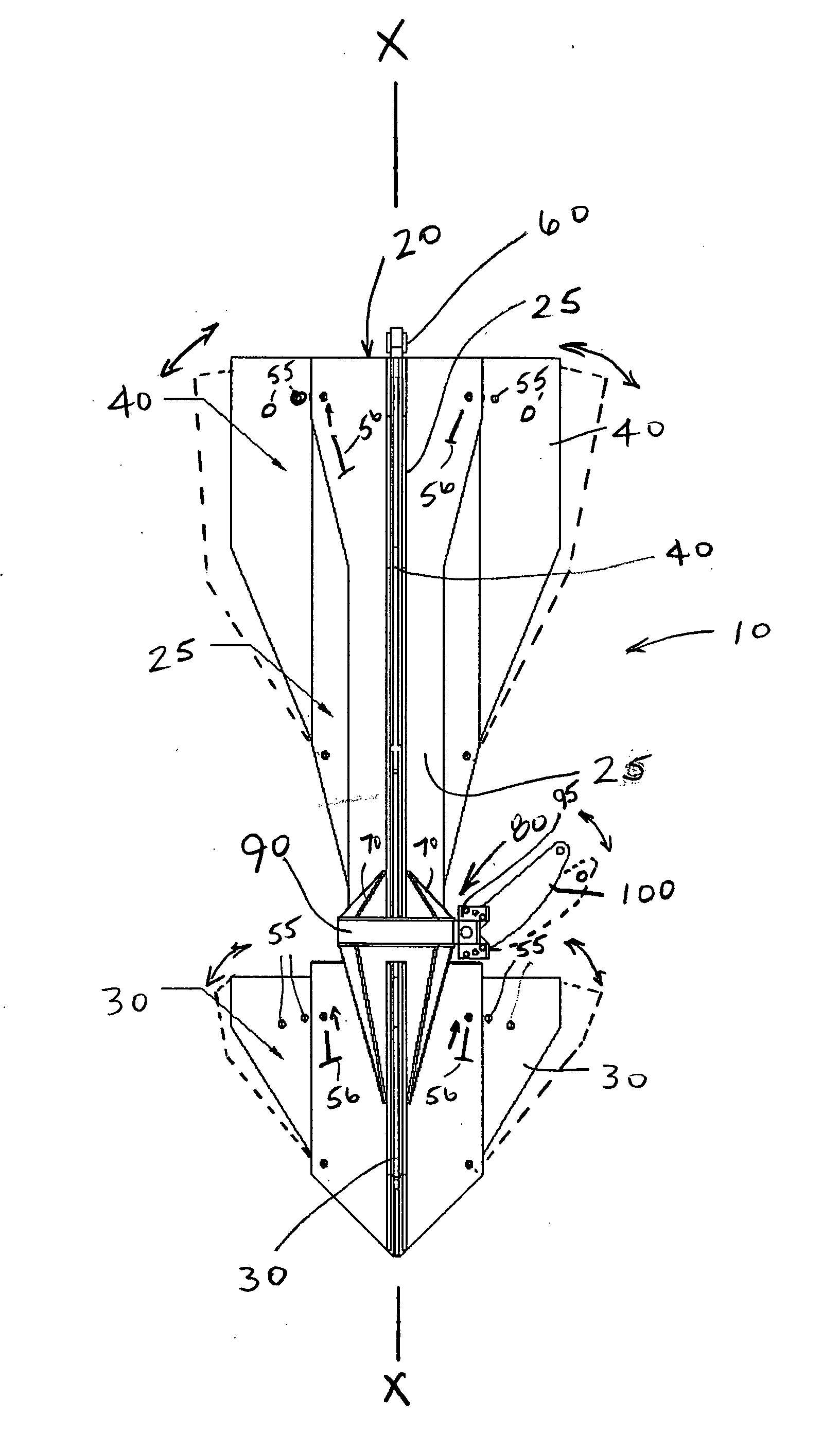
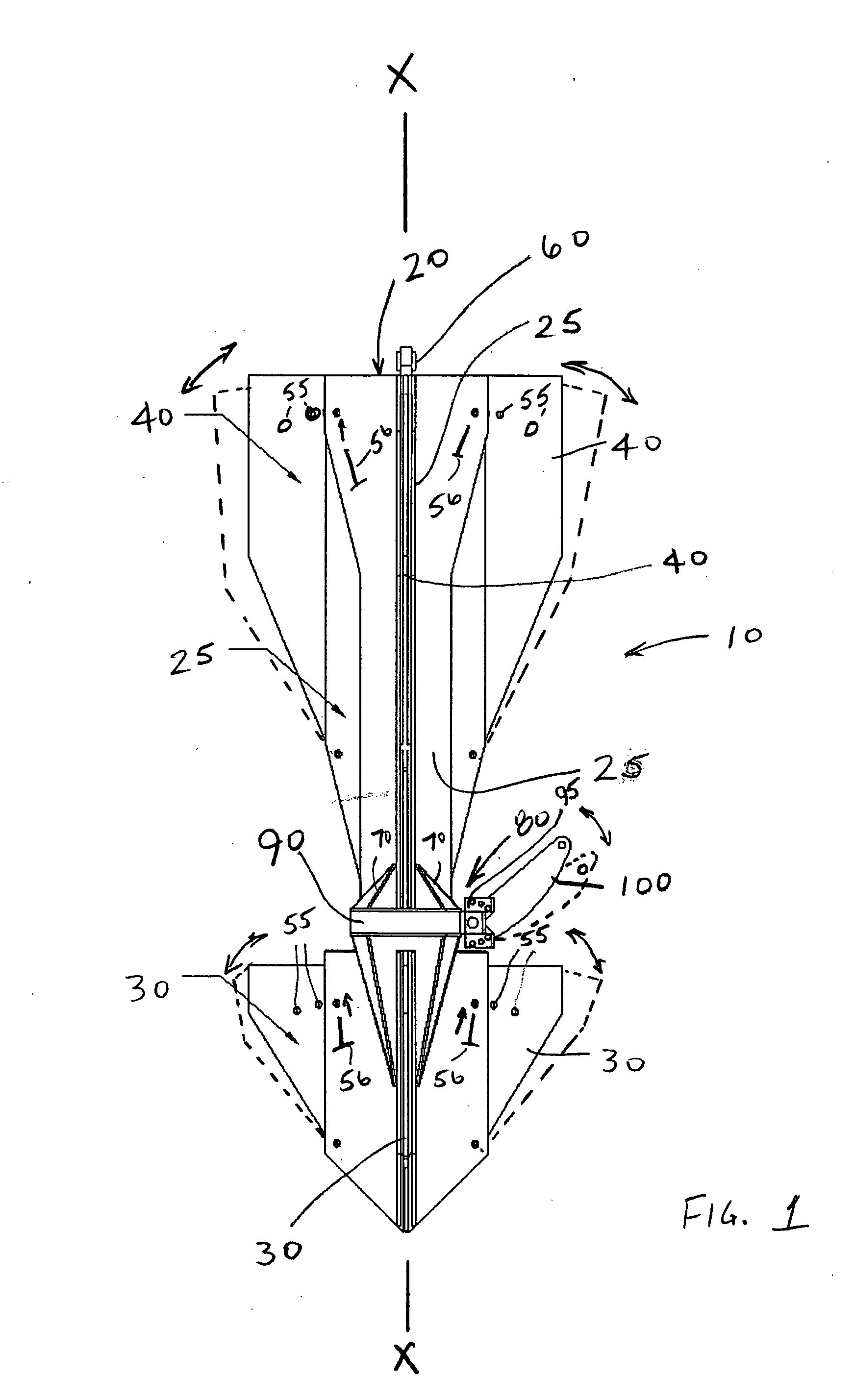
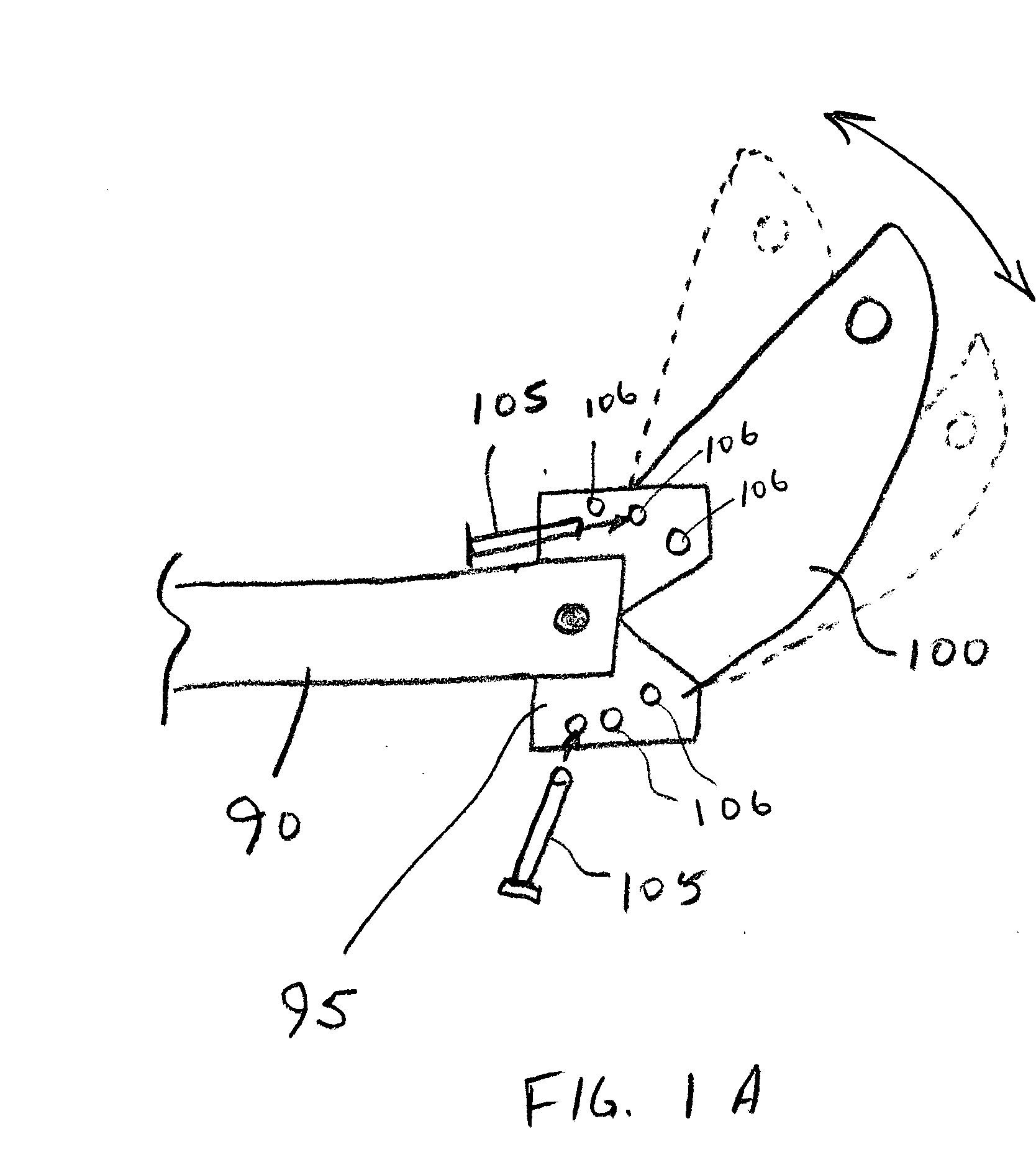
[0007] In addition, mooring line attachment points to such anchor designs are limited to top (that is, the uppermost end) or fixed side attachments. Top attachments do not require any particular alignment with the mooring line direction since the pull can be from any direction; however, the top attachment greatly reduces holding capacity. Side attachments yield greater holding capacity, however current designs require accurate attachment point orientation (that is, the attachment point must be aligned with the direction of mooring line pull). Angular alignment of the side attachment point with the mooring line pull can be difficult to achieve in field applications. The present invention preferably comprises a mooring line attachment which can rotate completely around the body of the anchor, and further comprises a hinged arm, eliminating problems related to installation orientation. Further, the arm reduces the likelihood of the mooring line being caught on the anchor plates. Yet another advantage of the present invention is that a single anchor can be adjusted to vary the exposed nose and tail plate areas, thereby rendering the anchor suitable for various applications, soil types, or soil strength gradients.
[0008] The anchor of the present invention, in a presently preferred embodiment, comprises an elongated central body having a longitudinal axis through its center. The central body comprises a plurality of channel members radiating outward from the center, each with a channel therein. A plurality of nose and tail plates are disposed within the channels, and hingedly connected to the central body, so that the plates can be rotated in or out from the central body, and thereafter fixed in place (for example, by pins inserted through mating holes in the channel members and plates). A means for attaching a mooring line to the anchor, for example a load ring assembly comprising a load ring encircling the central body and rotatable completely around the circumference of the central body, has a bracket thereon and an arm hingedly attached thereto. The arm can be rotated to a desired angle with respect to the longitudinal axis of the central body, and fixed in a set angle or within a range of angles to the longitudinal axis.

Problems solved by technology

One disadvantage of the prior art gravity-installed anchor designs is that a significant amount of penetration into the soil is required for adequate holding capacity.
In addition, mooring line attachment points to such anchor designs are limited to top (that is, the uppermost end) or fixed side attachments.
Top attachments do not require any particular alignment with the mooring line direction since the pull can be from any direction; however, the top attachment greatly reduces holding capacity.
Angular alignment of the side attachment point with the mooring line pull can be difficult to achieve in field applications.
Further, the arm reduces the likelihood of the mooring line being caught on the anchor plates.

Method used


Image

  • Gravity installed anchor
  • Gravity installed anchor
  • Gravity installed anchor

Examples


Embodiment Construction

[0016] Those having skill in the relevant art will recognize various changes which may be made to the embodiments disclosed herein, without departing from the nature and spirit of the invention. For illustrative purposes, some of the presently preferred embodiments of the invention will now be described, with reference to the drawings.

[0017]FIGS. 1-3 show the key structural elements of the anchor. Anchor 10 comprises an elongated central body 20 having a longitudinal axis X and comprising a plurality of radially outwardly extending channel members 25, as especially seen in FIGS. 2 and 3. While the particular embodiment shown comprises three channel members, each spaced 120 degrees apart from one another around the entire circumference, it is understood that two, four, or more channel members could be used. In comparison to the generally circular in cross section main shafts of certain prior art anchors, in certain applications the multiple channel member central body is a more capa...


PUM


Abstract

An anchor for mooring of structures to a water bottom, comprising an elongated central body having a longitudinal axis through its center. The central body comprises a plurality of channel members radiating outward from the center, each with a channel therein. A plurality of nose and tail plates are disposed within the channels, and hingedly connected to the central body, so that the plates can be swung in or out from the central body, and thereafter fixed in place (for example, by pins inserted through mating holes in the channel members and plates). A means for attaching a mooring line to the anchor, for example a load ring encircling the central body and rotatable completely around the circumference of the central body, has an arm hingedly attached thereto. The arm can be rotated to a desired angle with respect to the longitudinal axis of the central body, and fixed at a set angle or within a range of angles to the longitudinal axis.

Description

CROSS REFERENCE TO RELATED APPLICATIONS [0001] This regular patent application claims priority to provisional patent application titled “Gravity Installed Anchor,” inventor Evan H. Zimmerman, filed Nov. 11, 2004.BACKGROUND [0002] 1. Field of the Invention [0003] This invention relates to apparatus used in the mooring of structures to the soils underlying bodies of water, referred to as waterbottoms. More specifically, this invention relates to a type of anchor particularly, although not exclusively, suitable for so-called “gravity installation,” where the anchor is released at a desired height above a water bottom and allowed to fall to and penetrate into the waterbottom. [0004] 2. Description of Related Art [0005] Different types of anchors, especially suited for the mooring of floating structures, have long been in use. Some anchors rely on their weight for holding capacity. Others have flukes which tend to drive the anchor into the waterbottom when a tension is applied to a moori...

Claims


Application Information

Patent Timeline
Patent Type & Authority Applications(United States)
IPC IPC(8): B63B21/00
CPCB63B21/243B63B21/26B63B21/29B63B2021/262B63B2021/265
Inventor ZIMMERMAN, EVAN H.
Owner DELMAR SYST
Learn More