Fuel injection pump with cold start device

Active Publication Date: 2006-05-25
YANMAR CO LTD
View PDF11 Cites 2 Cited by
  • Summary
  • Abstract
  • Description
  • Claims
  • Application Information

AI Technical Summary

Benefits of technology

[0009] According to the invention, a fuel injection pump comprises: a barrel formed with a main port and a sub port; a plunger; and a cold start device including an injection-advancing actuator which operates a piston for operating or closing the sub port so as to change an injection timing in correspondence to temperature. The plunger is moved to connect or separate the sub port and the main port t and from a fuel compression chamber. The barrel is further formed with at least one exclusive overflowing sub port constantly opening regardless of the operational state of the piston. The exclusive overflowing sub port is disposed between the main port and the sub port opening and closed by the piston in the slide direction of the plunger so that the positional difference of the sub port being able to be opened and closed and the exclusive overflowing sub port in the slide direction of the plunger defines the change degree of injection timing. The position and diameter of the exclusive overflowing sub port are adjusted to adjust the change degree of injection timing and quantity. Due to the positional setting of the exclusive overflowing sub port, the change degrees of the advanced injection timing and quantity during closing of the overflowing sub port (activation of the CSD) from those during opening of the overflowing sub port (inactivation of the CSD) can be optionally decided so as to optimize the engine start-up during activation of the CSD (in a low temperature or a cold engine condition) while ensuring the engine characteristic during inactivation of the CSD (in a normal temperature or a warmed engine condition). Further, while ensuring the engine characteristic during inactivation of the CSD (in a normal temperature or a warmed engine condition), has small change degrees of the advanced injection timing and quantity during closing of the overflowing sub port (activation of the CSD) in comparison with the conventional fuel injection pump. In this way, the engine start-up in a low temperature, NOx and black smoke in exhaust gas and noise can be reduced and the start-up time can be shortened, thereby improving the general engine performance.

Problems solved by technology

This is the reason why optimization of the engine start-up during activation of the CSD (in a low temperature or a cold engine condition) while ensuring the require engine performance during activation of the CSD (in a normal temperature or a warmed engine condition) is difficult.

Method used


Image

  • Fuel injection pump with cold start device
  • Fuel injection pump with cold start device
  • Fuel injection pump with cold start device

Examples


Embodiment Construction

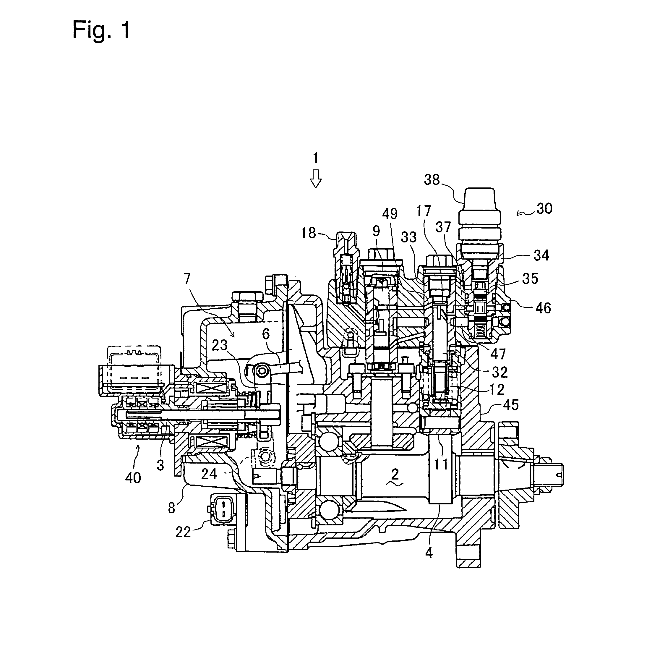
[0016] A fuel injection pump 1 according to the invention is mounted on a diesel engine. An embodiment of fuel injection pump 1 will be described on the assumption that the left side of FIG. 1 is regarded as the front side of fuel injection pump 1.

[0017] As shown in FIG. 1, fuel injection pump 1 comprises a pump housing 45 and a hydraulic head 46 which are vertically joined to each other. A casing 8 of an electronic governor 7 is attached onto a front side surface of pump housing 45. A rack actuator 40 is fixedly inserted rearward into casing 8. Governor 7 does not have to be an electronic governor, and may be replaced with a mechanical governor.

[0018] Rack actuator 40 moves a slide shaft 3 forward or rearward. Slide shaft 3 is pivotally connected at a tip thereof to an intermediate portion of a governor lever 23.

[0019] Governor level 23 is pivoted at a lower portion thereof on a governor lever shaft 24. A link 6 is pivotally connected to a top portion of governor lever 23, so th...


PUM


Abstract

A fuel injection pump comprises: a barrel formed with a main port 39 and a sub port 36a; a plunger 32; and a CSD 30 including an injection-advancing actuator 38 which operates a piston 35 for opening or closing sub port 36a so as to change an injection timing. Plunger 32 is moved to connect or separate sub port 36a and main port 39 to and from a fuel compression chamber 17. The barrel is further formed with at least one exclusive overflowing sub port 36b constantly opened regardless of the operational state of the piston 35.

Description

CROSS-REFERENCE TO RELATED APPLICATION [0001] The present application is a Continuation of PCT Application No. PCT / JP2004 / 006221, filed Apr. 28, 2004, which is hereby incorporated in its entirety herein by reference thereto.BACKGROUND OF THE INVENTION [0002] 1. Field of the Invention [0003] The present invention relates to a fuel injection pump with a cold start device for advancing fuel injection to a diesel engine when being started up in a low temperature, and particularly, to a technology for optimizing the fuel injection timing and quantity during the engine start-up in a low temperature. [0004] 2. Background Art [0005] Conventionally, there are well-known fuel injection pumps for diesel engines, each comprising a plunger, a plunger barrel, a distribution shaft, and delivery valves, wherein the plunger is vertically reciprocated in the plunger barrel to discharge compressed fuel to the distribution shaft, the distribution shaft distributes the fuel from the plunger among the de...

Claims


Application Information

Patent Timeline
IPC IPC(8): F02M37/04F02M59/26F02M59/32F02M59/36
CPCF02M59/265F02M59/32F02M59/366F02M59/36
Inventor TANAKA, MASAMICHI
Owner YANMAR CO LTD
Why Eureka
Try Eureka