Device for influencing gas flows

a technology of gas flow and device, which is applied in the direction of respirator, inhalator, medical atomiser, etc., can solve the problems of filter resistance increasing so much that it closes, special difficulties arise in the utilization of aerosols, and loses its antibacterial

Inactive Publication Date: 2006-05-25
RIST MAX
View PDF8 Cites 22 Cited by
  • Summary
  • Abstract
  • Description
  • Claims
  • Application Information

AI Technical Summary

Problems solved by technology

However, special difficulties arise with the utilization of aerosols with patents receiving artificial respiration.
The heavy humidification of the non-utilized gas column (dead space volume), mostly with large aerosol particles, causes the filter to become filled with liquid and thus loses its antibacterial effect on the one hand, while, on the other hand, the resistance of the filter increases so much that it closes up.
However, these devices can only be placed in the inspiration leg of an artificial respirator since they produce aerosols continuously and would thus convey aerosols to or from the patient during the inspiration as well as during the expiration phase.
A filter would, therefore, fill up and lose effectiveness or close up.
By omitting a filter, insufficient humidification of the breathing or inhaled air results so that a breathing-air humidifier has to be used which, in addition to costs, also involves a hygienic problem (nosocomial pneumonia).

Method used


Image

  • Device for influencing gas flows
  • Device for influencing gas flows
  • Device for influencing gas flows

Examples


Embodiment Construction

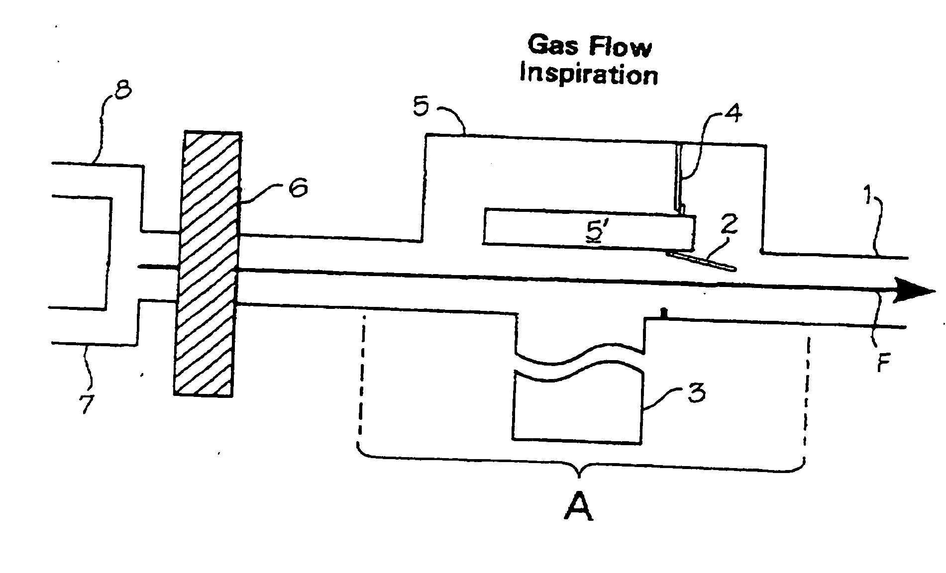
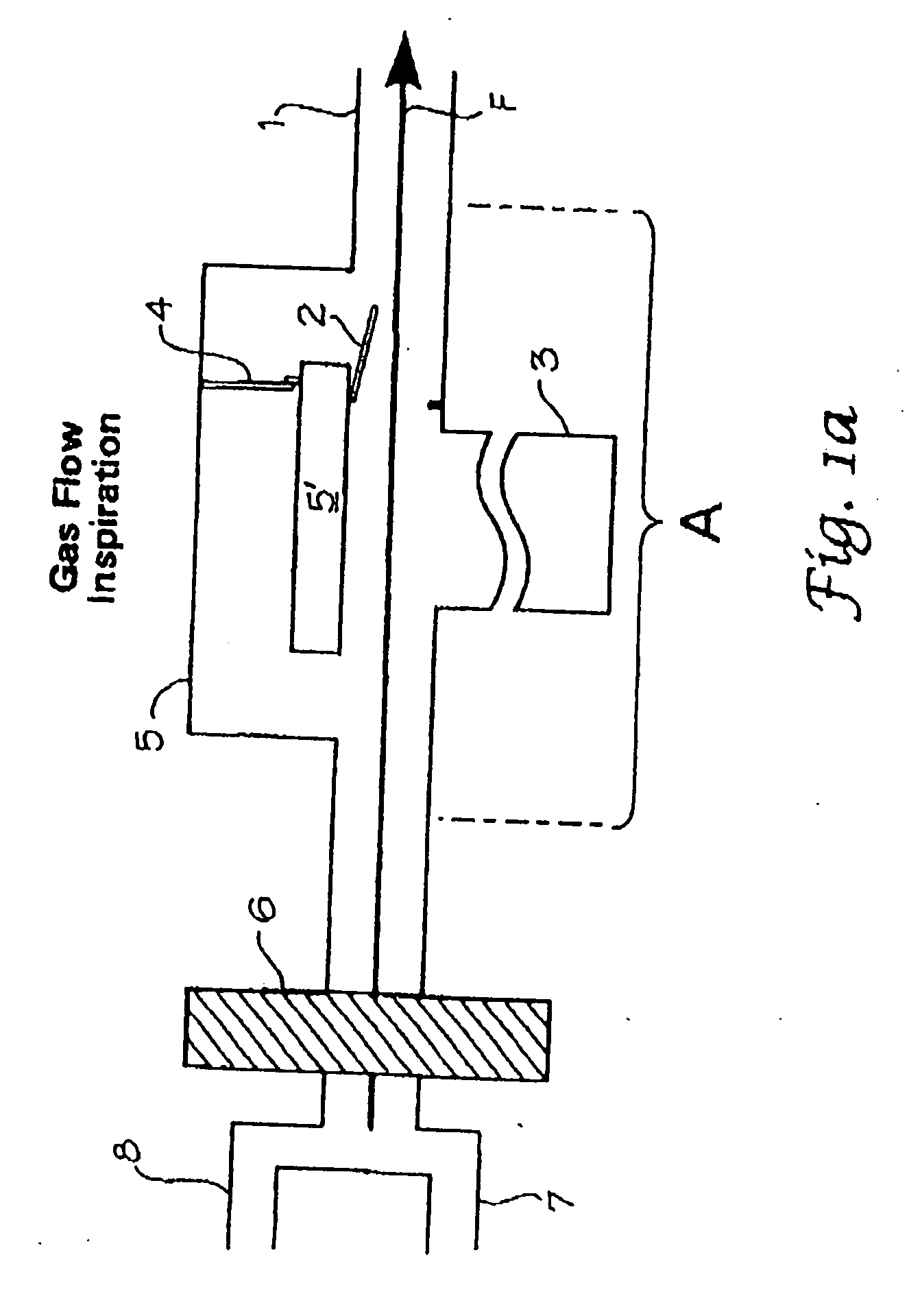
[0011] My invention makes it possible to place the atomizer (any atomizer can be used) between a filter and tube barrel without a breathing air humidifier at the common end segment of a respirator with the advantage of lower consumption of medicine, fewer side-effects due to applied medicines and longer life of the filter. This is done in the following manner in one embodiment:

[0012] The breathing air is conveyed through an atomizer via closing valves (passively or actively controlled as indicated). To make this possible, the valves can be placed at different points in this device. The possibility also exists to use auxiliary devices (e.g., ventilators) in order to optimize the distribution of the aerosol.

[0013] In another embodiment, a control cable or hose causes a valve to open in response to the volume of breath, the duration of inspiration, and the pressure of inspiration, so that the dead space is not filled with aerosol. The possibility also exists in this embodiment to use...


PUM


Abstract

The invention relates to a device for controlling and guiding gas flow in atomizers, in breathing and rebreathing regions of a respiratory appliance. A first embodiment comprises a bypass device; and a said second embodiment comprises a valve which is timed by the respiratory appliance, such that the dead space is not filled with aerosol. Both embodiments provide for an application of aerosol only in the inspiration phase, reduction of the applied medication quantity by reducing the atomization of the dead space, reduction of the side effects of the medications, and sufficient moisturizing of the airways.

Description

FIELD OF THE INVENTION [0001] This invention relates to respirator appliances and specifically to controlling and guiding the flow of gas within such appliances. BACKGROUND OF THE INVENTION [0002] With patients suffering from pulmonary diseases, aerosols are often used for therapy. However, special difficulties arise with the utilization of aerosols with patents receiving artificial respiration. Either compressed-air operated nozzle atomizers or atomizers producing aerosols continuously, such as, e.g., ultrasound atomizers or piezoelectric atomizers are used. The nozzle atomizers are normally placed in the common end segment for inspiration and expiration of the artificial respiration hoses, shortly before the tube barrel and are controlled via the artificial respirator, so that they are active only during inspiration. An atomizer is, however, active until the end of inspiration, so that in the overall hose system distal gas enriched with aerosol is present in the atomizer so that t...

Claims


Application Information

Patent Timeline
Patent Type & Authority Applications(United States)
IPC IPC(8): A61M11/00B05B7/00A61M16/08A61M16/10
CPCA61M11/00A61M16/08A61M16/14A61M16/208A61M16/1065A61M16/107A61M16/202
Inventor RIST, MAX
Owner RIST MAX
Why Eureka
Try Eureka