Pressure regulator with ceramic valve element

a technology of ceramic valve element and pressure regulator, which is applied in the direction of functional valve types, ring springs, machines/engines, etc., can solve the problems of high density metallic valve element that can wear the sealing surface of the valve seat, require a substantial number of parts, and reduce the noise generation improve noise and flow characteristics of fuel pressure regulators, and reduce materials and manufacturing costs

Inactive Publication Date: 2006-05-25
VITESCO TECH USA LLC
View PDF27 Cites 20 Cited by
  • Summary
  • Abstract
  • Description
  • Claims
  • Application Information

AI Technical Summary

Benefits of technology

[0011] In accordance with another aspect of this invention, a method for reducing noise generation in a flow through pressure regulator, the method comprising: providing a passage for a fuel flow from a fuel inlet to a fuel outlet wherein a valve element prohibits the fuel flow through the passage; and communicating the fuel flow with a va

Problems solved by technology

A high density metallic valve element has the potential to wear the sealing surface of the valve seat, which is also called galling.
This wear can be attributed to the valve element impacting the valve seat

Method used


Image

  • Pressure regulator with ceramic valve element
  • Pressure regulator with ceramic valve element
  • Pressure regulator with ceramic valve element

Examples


Embodiment Construction

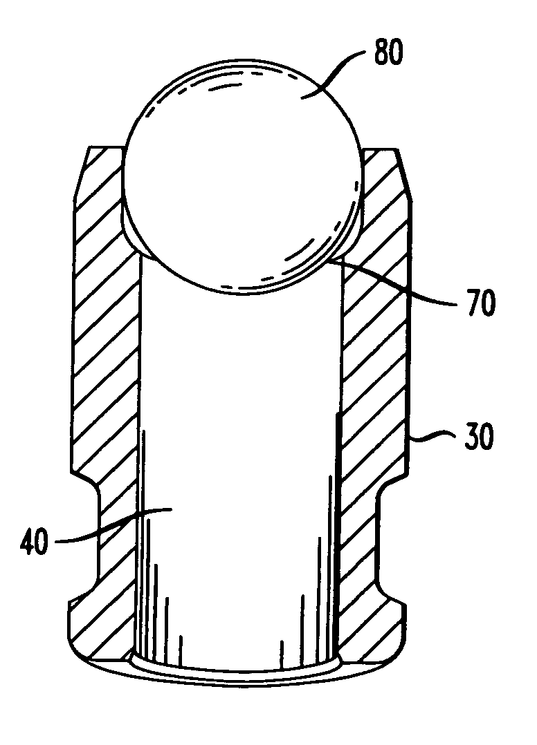
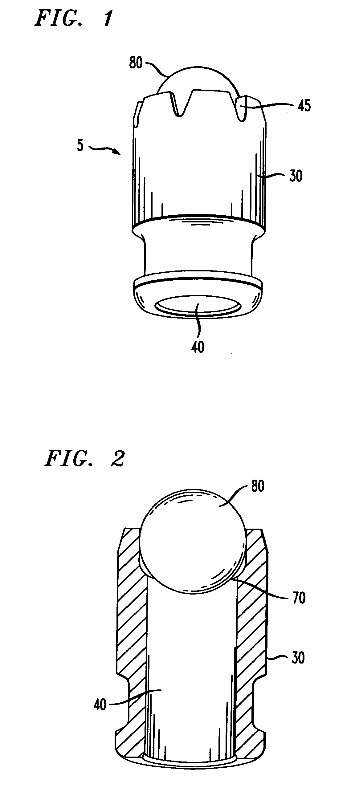
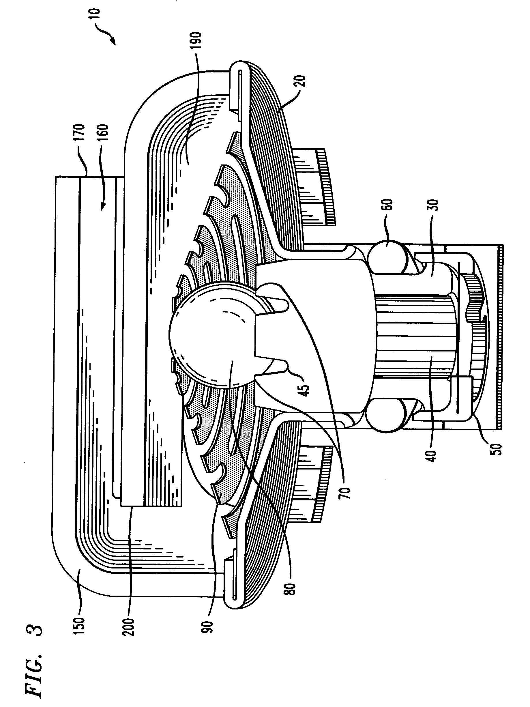
[0021]FIGS. 1, 2, and 3 illustrate a flow through pressure regulator 10 according to the present invention. Flow through pressure regulator 10 includes a lower housing 20 that contains a fuel tube 30. Fuel tube 30 houses a fuel chamber 40 which is generally cylindrical in shape and which channels the fuel into the pressure regulator 10 from the fuel pump (not shown). In the preferred embodiment, fuel tube 30 is made from stainless steel. Fuel will first pass through a fuel filter 50 into fuel chamber 40. Fuel filter 50, generally circular in shape, it is disposed around lower portion of fuel tube 30 and adjacent to an o-ring 60. O-ring 60 is positioned below the lower housing 20 to seal and prevent any fuel leakages into other components in the system. O-ring 60 is made of an elastomeric material and is generally circular in shape. Others skilled in the art may select not to use an o-ring 60.

[0022] Flow through pressure regulator 10 also includes a valve seat 70 which cooperates wi...


PUM


Abstract

A flow through pressure regulator apparatus and method for directing a flow of fuel within a fuel system. Present invention includes a lower housing having a fuel inlet where fuel flows through the fuel inlet and communicates with a valve biasing member through a fuel chamber and lower valve element with fuel passages. The valve biasing member permits or inhibits fuel flow through a fuel chamber by opening and closing a ceramic valve element. The valve biasing member comprises a flat disk having at least two reticulated concentric rings coupled by at least one bridge. The fuel flows past an open valve element through the lower valve element fuel passages to the valve biasing member. The valve biasing member then diffuses the flow of fuel. A fuel cover directs the flow of fuel from the valve biasing member to the fuel outlet.

Description

CROSS REFERENCE OF RELATED APPLICATIONS [0001] This application claims priority to, and incorporates by reference herein in its entirety, pending U.S. Provisional Patent Application Ser. No. 60 / 632,094 (Attorney Docket No. 2004P20208US), filed 1 Dec. 2004. This application is a continuation in part of U.S. patent application Ser. No. 10 / 997,654 (Attorney Docket No. 2004P13150US), filed 24 Nov. 2004, the entirety of which is incorporated by reference.FIELD OF INVENTION [0002] This invention relates to pressure control devices in general and more particularly, a pressure control device comprising a valve assembly including a ceramic valve element used in automotive fuel systems. BACKGROUND [0003] Most modern automotive fuel systems use fuel injectors to deliver fuel to the engine cylinders for combustion. The fuel injectors are mounted on a fuel rail to which fuel is supplied by a pump. The pressure at which the fuel is supplied to the fuel rail must be metered to ensure the proper op...

Claims


Application Information

Patent Timeline
IPC IPC(8): F16K17/00
CPCF16K15/046F16K17/0406F16K17/0493F16K25/005Y10T137/7927
Inventor ETHERIDGE, DAWN M.MORRIS, JAMES RUSSELLWYNN, JAMES ARCHIE JR.
Owner VITESCO TECH USA LLC
Why Eureka
Try Eureka