Panel assembling apparatus and panel assembling method

Inactive Publication Date: 2006-05-25
PANASONIC CORP
View PDF1 Cites 7 Cited by
  • Summary
  • Abstract
  • Description
  • Claims
  • Application Information

AI Technical Summary

Benefits of technology

[0041] According to the fifth aspect of the invention, the support member is expanded and contracted by the relative movement of the substrate mounting table and the panel mounting table. That is, no actuator such as a motor for moving the support member is unnecessary. This simplifies t

Problems solved by technology

In such an electronic component, the auxiliary substrate usually droops from the panel substrate owing to the self-weight.
This has caused a problem that when the arm of the ejection unit described above enters

Method used


Image

  • Panel assembling apparatus and panel assembling method
  • Panel assembling apparatus and panel assembling method
  • Panel assembling apparatus and panel assembling method

Examples


Embodiment Construction

[0072] Before the description of the present invention proceeds, it is to be noted that like parts are designated by like reference numerals throughout the accompanying drawings.

[0073] Embodiments of the invention are described below in detail with reference to the drawings.

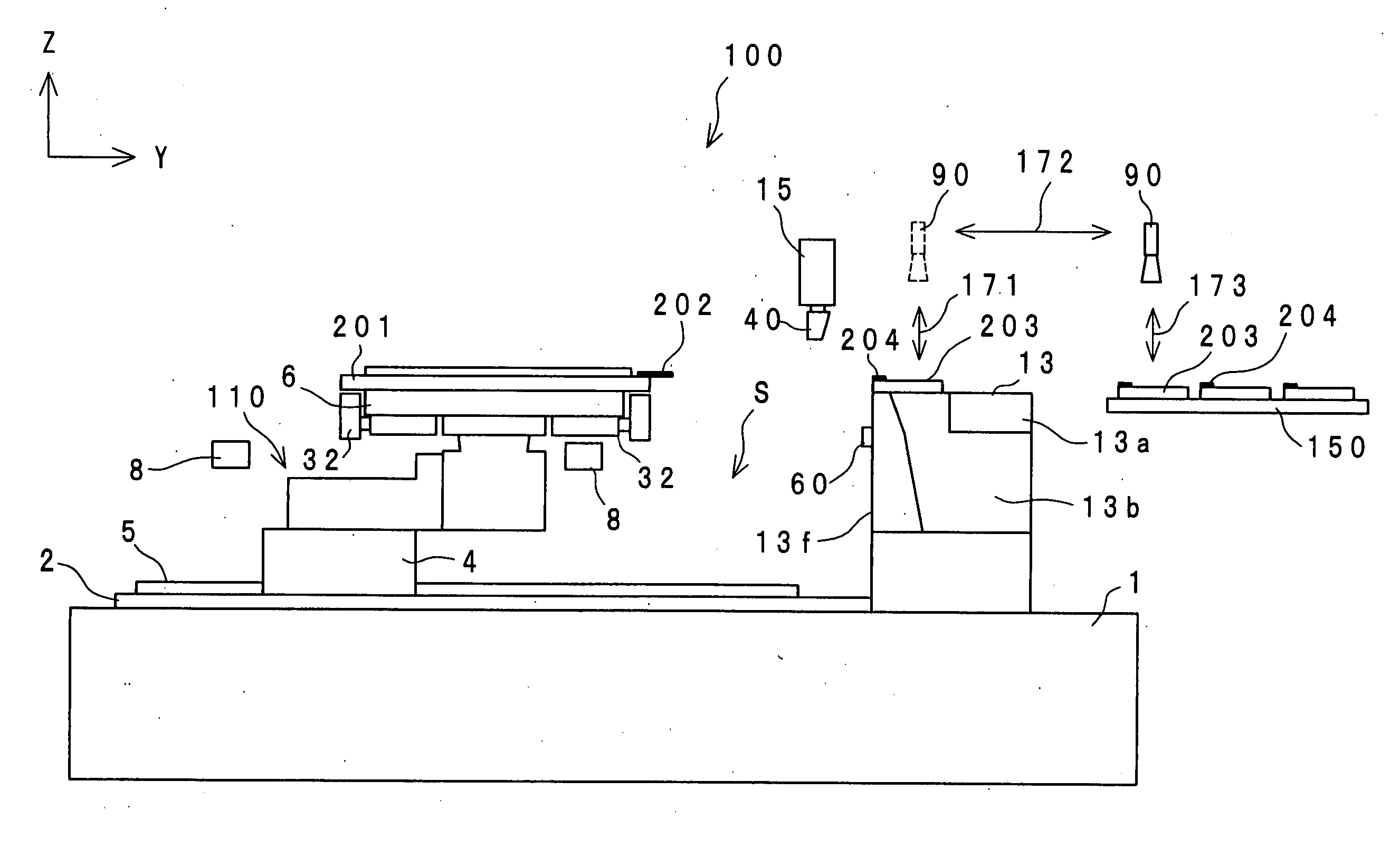
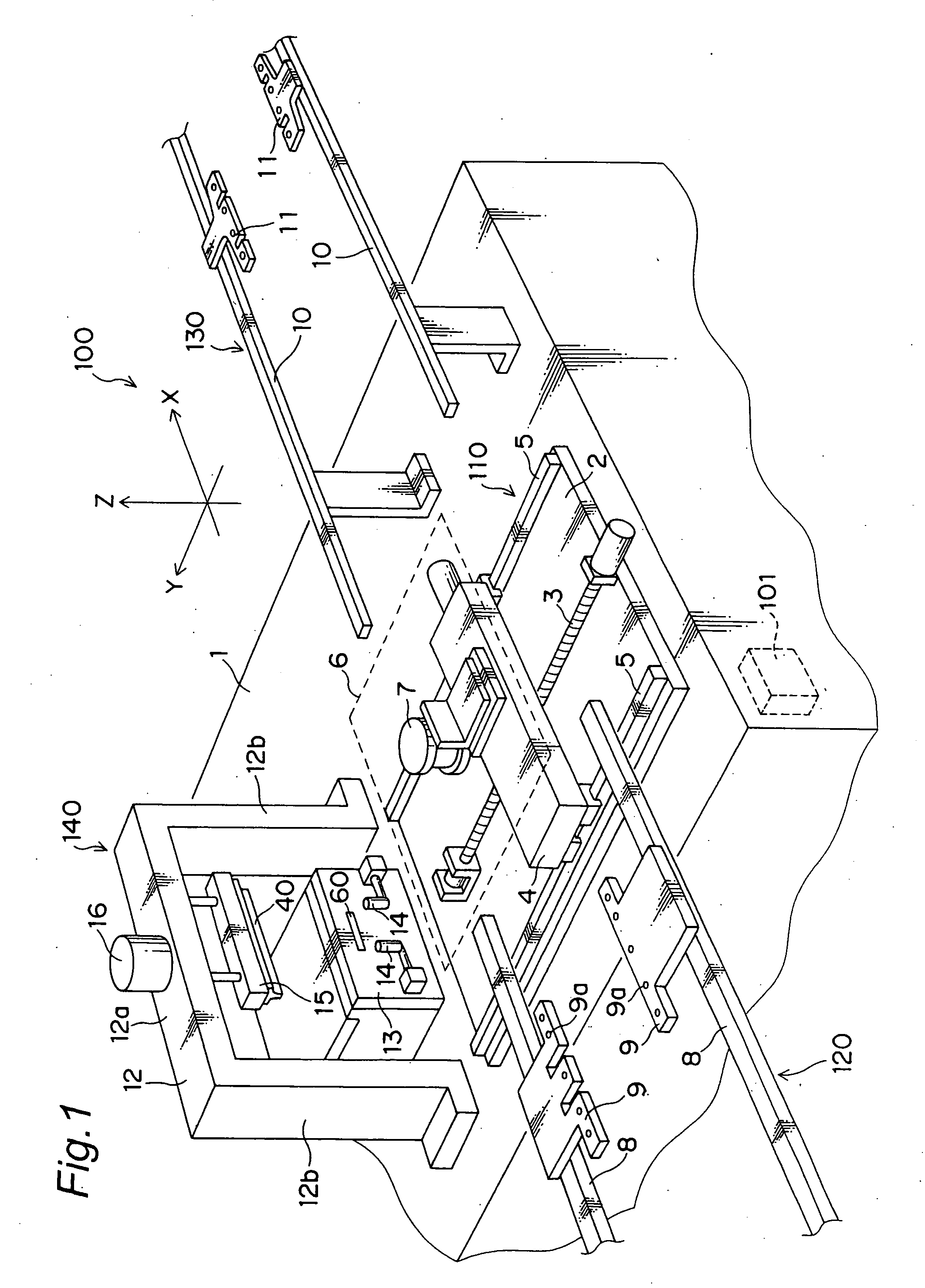
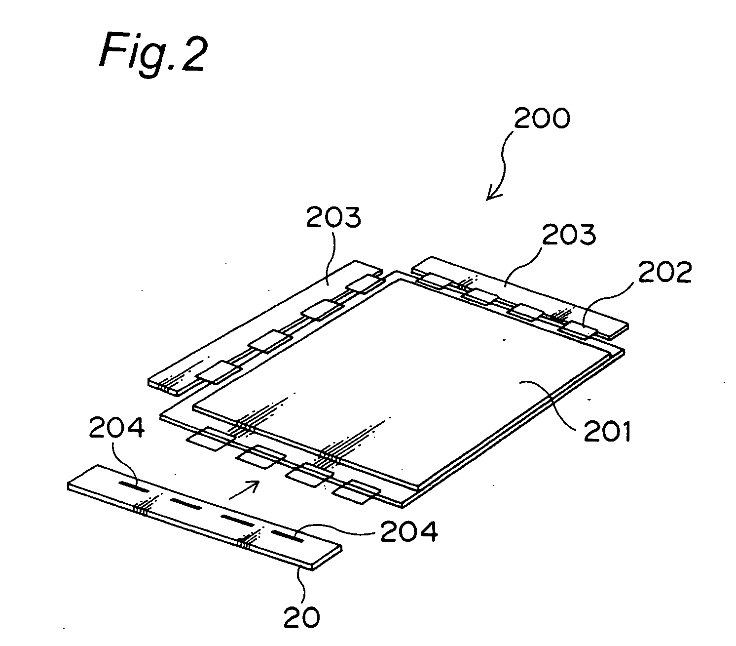
[0074]FIG. 1 is a perspective view showing external appearance configuration of a panel assembling apparatus according to an embodiment of the invention. The panel assembling apparatus according to the present embodiment is an apparatus shown in FIG. 2 for assembling a display 200 used as a liquid crystal display panel, a plasma display panel, an organic EL display panel, or the like. More specifically, this apparatus attaches via a flexible substrate 202 an auxiliary substrate 203 to each of a plurality (three in FIG. 2) of outer edges of a panel substrate 201 having a rectangular shape. Each flexible substrate 202 for TAB or the like is bonded in a manner protruding beyond the outer edge of the panel substrat...


PUM

PropertyMeasurementUnit
Pressureaaaaaaaaaa
Flexibilityaaaaaaaaaa

Abstract

In a case that a panel substrate to which a flexible substrate is bonded in a protruding manner is to be bonded by pressure to an auxiliary substrate, the panel substrate and the auxiliary substrate are placed on a panel mounting table and a substrate mounting table, respectively. Then, both mounting tables are moved such that the protruding portion of the flexible substrate should be located at the bonding position of the auxiliary substrate. Then, the flexible substrate and the auxiliary substrate are bonded by pressure by a pressure bonding head. When the auxiliary substrate bonded by pressure is removed from the substrate mounting table, a support member provided in the panel substrate mounting table supports directly the auxiliary substrate from the downside so that the auxiliary substrate should not droop relative to the panel substrate.

Description

BACKGROUND OF THE INVENTION [0001] The present invention relates to a panel assembling apparatus and a panel assembling method for bonding an auxiliary substrate to a substrate for a panel widely used as a display in electronic equipment. [0002] In recent years, displays in electronic equipment such as personal computers and television receivers employ a liquid crystal panel, a plasma display panel (PDP), an organic EL display panel, and the like. Such a display includes a transparent plate serving as a panel substrate. On its edge, a flexible substrate is bonded, while outer leads of the flexible substrate are bonded to electrodes of an auxiliary substrate, so that assembling is achieved. This flexible substrate is fabricated as a film carrier by a TAB (Tape Automated Bonding) method in many cases. [0003] In such a component mounting unit, in general, a panel substrate on which a flexible substrate is mounted is placed on a conveyance stage so that the auxiliary substrate is positi...

Claims


Application Information

Patent Timeline
IPC IPC(8): B31B1/60B32B37/00B29C65/00G02F1/13G09F9/00
CPCH01J9/241Y10T156/10Y10T156/1702H01J9/38H01J11/20
Inventor NAKANISHI, TOMOAKI
Owner PANASONIC CORP
Why Eureka
Try Eureka