
Control system for hybrid vehicle

a control system and hybrid technology, applied in the field of hybrid vehicles, can solve the problems of low efficiency in energy regeneration, low efficiency in engine brake assistance, low transmission efficiency, etc., and achieve the effect of reducing electric power consumption

Inactive Publication Date: 2006-05-25
HONDA MOTOR CO LTD
View PDF12 Cites 58 Cited by
  • Summary
  • Abstract
  • Description
  • Claims
  • Application Information

AI Technical Summary

Benefits of technology

The present invention provides a control system for a hybrid vehicle that can restrain the electric power consumption for the motor generator by limiting its cooperative operation with the engine. The control system detects the slip ratio of the torque converter and engages the lock-up clutch appropriately in response to the driving condition of the vehicle. The system engages the motor generator cooperatively with the torque converter and ratio-change mechanism to regenerate energy during deceleration, while preventing fluctuations in the driving torque that can be caused by the transmission of the torque applied by the motor generator. The control system is efficient in energy regeneration and prevents the driver from feeling incongruity during the driving experience.

Problems solved by technology

In a hybrid vehicle equipped with such an automatic transmission, while the vehicle is being decelerated (with the accelerator being released) with the force from the drive wheels being transmitted to the motor generator, slips are likely to occur in the torque converter, resulting in a low transmission efficiency.
This condition leads to problems of low efficiency in energy regeneration, low effectiveness in engine brake assistance and the like.
However, if a shifting is executed while the lock-up clutch is engaged for improving the energy regeneration efficiency, then there can be a sudden change in the braking force (so-called engine brake force), which may give a sense of incongruity to the driver.

Method used


Image

  • Control system for hybrid vehicle
  • Control system for hybrid vehicle
  • Control system for hybrid vehicle

Examples


example 1

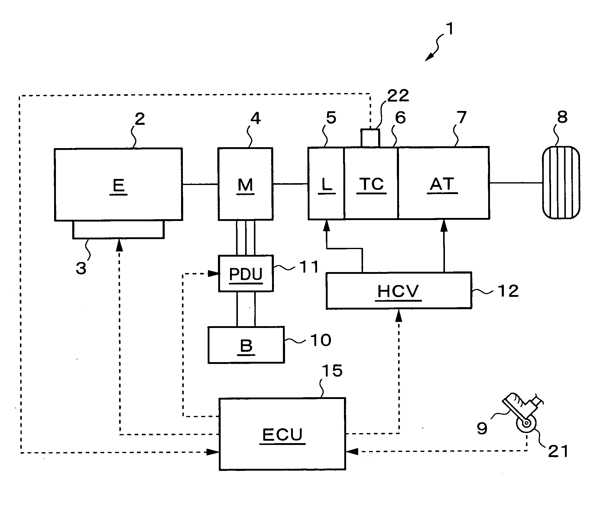
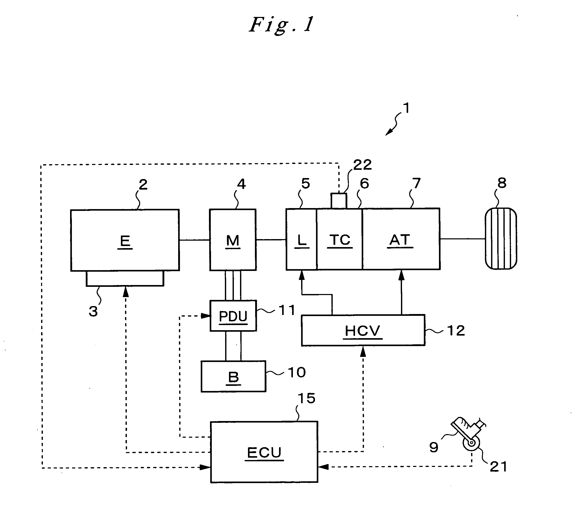
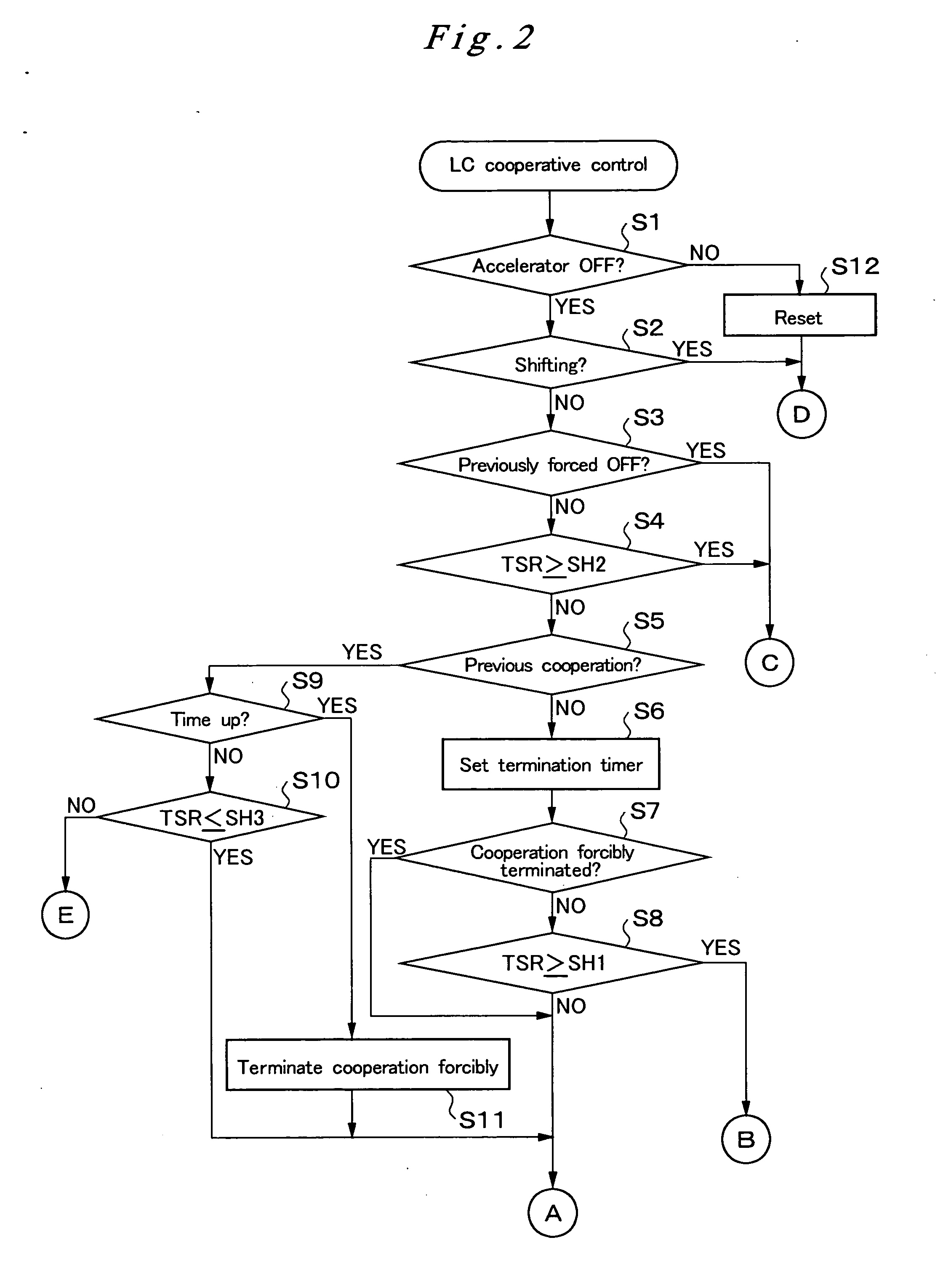
[0074] In the first example, which is shown in FIG. 5, when the accelerator is judged as being off at time t1, no shifting is being executed, and no forced release of the lock-up clutch has been executed recently. For this situation, the control flow shown in FIG. 2 proceeds from step S1 to step S2 and step S3 to step S4. In this instance, the engine rotational speed Ne (=the input rotational speed of the torque converter Nti) is higher than the rotational speed Nm of the input shaft of the transmission (=the output rotational speed Nto of the torque converter) as shown in (B). Therefore, the slip ratio TSR of the torque converter 6 is smaller than 100%, and TSR2 (with SH2=120%) as shown in (C). As a result, the control flow proceeds to step S5.

[0075] In addition, no cooperative operation has been executed recently, and no forced termination of the cooperative operation has been executed recently. As a result, the control flow proceeds from step S5 to step S6, where the termination...

example 2

[0079]FIG. 6 shows a second example. In this example, the conditions at time t1 are the same as the first example, so the control flow proceeds to step S14 and to step S15, where the deceleration lock-up control is initiated without execution of the cooperative operation of the motor generator 4. As a result, the lock-up clutch control pressure PLC, which is supplied to the lock-up clutch 5, is increased at time t1 and thereafter as shown in (D), for starting the control of bringing the lock-up clutch 5 into engagement. Because the accelerator is turned off, the rotational speed Ne of the engine decreases greatly beyond the rotational speed Nm of the input shaft of the transmission, and the slip ratio TSR increases above the first threshold value SH1 at time t2 as shown in (C).

[0080] Therefore, the control flow proceeds from step S8 to step S16 and to step S17, where the cooperative lock-up control is executed, and the cooperative operation of the motor generator 4 is executed. In ...

example 3

[0083]FIG. 7 shows a third example. Also in this example, the conditions at time t1 are the same as the first example, so the control flow proceeds to step S14 and to step S15, where the deceleration lock-up control is initiated without execution of the cooperative operation control of the motor generator 4. As a result, the lock-up clutch control pressure PLC, which is supplied to the lock-up clutch 5, is increased at time t1 and thereafter as shown in (D), for starting the control of bringing the lock-up clutch 5 into engagement. Because the accelerator is turned off, the rotational speed of the engine decreases greatly beyond the rotational speed Nm of the input shaft of the transmission, and the slip ratio TSR increases above the first threshold value SH1 at time t2 as shown in (C).

[0084] Therefore, the control flow proceeds from step S8 to step S16 and to step S17, where the cooperative lock-up control is executed, and the cooperative operation of the motor generator 4 is exec...


PUM


Abstract

A hybrid vehicle comprises an engine 2, a motor generator 4, a torque converter 6 with a lock-up clutch 5, and a ratio-change mechanism 7. A control system for the hybrid vehicle comprises a rotational sensor 22, which detects the slip ratio of the torque converter, and a hydraulic control valve 12, which controls the engagement of the lock-up clutch. While the vehicle is moving along with the accelerator pedal being released from its stepped down condition, a driving force from the wheels is transmitted to the motor generator 4 for energy regeneration. If the slip ratio of the torque converter is equal to or smaller than a first threshold value, then only the lock-up clutch is controlled into engagement. However, if the slip ratio is between the first threshold value and a second threshold value, then additionally the motor generator is controlled in cooperative operation.

Description

FIELD OF THE INVENTION [0001] The present invention relates to a hybrid vehicle that comprises an engine, a motor generator, a torque converter with a lock-up clutch, and a ratio-change mechanism and that is driven by the driving force of at least one of the engine and the motor generator, the driving force being transmitted to drive wheels through the torque converter and the ratio-change mechanism. BACKGROUND OF THE INVENTION [0002] Such hybrid vehicles are disclosed in, for example, Japanese Laid-Open Patent Publication Nos. H6(1994)-319210, H9(1997)-322307, H10(1998)-73161, 2003-205767, 2004-84679 and 2004-210123. As described in these disclosures, various types of hybrid vehicle have been proposed. For example, the following ideas are incorporated in a system where the vehicle is driven by the driving force being transmitted to drive wheels from both the engine and the motor generator or selectively from one or the other, i.e., a system where the engine and the motor generator ...

Claims


Application Information

Patent Timeline
Patent Type & Authority Applications(United States)
IPC IPC(8): B60K6/00B60K6/485
CPCB60K6/485B60W10/06B60W10/08B60W10/11B60W20/00B60W2510/0241F16H61/143F16H2059/467Y02T10/6226Y02T10/6286Y02T10/62B60W10/026
Inventor KITANO, KAZUHIKOKIMURA, MASACHIKAIJICHI, YASUHIROISHIKAWA, YUTAKAHORIGUCHI, TAKASHI
Owner HONDA MOTOR CO LTD
Learn More