Image pickup module and manufacturing method of image pickup module

Inactive Publication Date: 2006-05-25
SHARP KK
View PDF12 Cites 27 Cited by
  • Summary
  • Abstract
  • Description
  • Claims
  • Application Information

AI Technical Summary

Benefits of technology

[0051] In this invention, by further fixing the contact section and the transparent body together, the positional relationship between the fixing section and the transparent body does not vary, thereby producing advantageous effects, such as reducing the possibility of displacement of the position of the lens mounted in the fixing section with respect to the transparent body, and more firmly controlling the optical position of incident light.

Problems solved by technology

Thus, a long time is required to manufacture the image pickup module, and the cost increase is accelerated.
Thus, this structure is not quite sufficient for the simplification of the mounting process and improvement in focus accuracy.
Further, although the figure tolerance of the surface of the substrate as the positioning reference is important, in general, the surface of the substrate has irregularity, and therefore a smoothing process is necessary and causes a problem of cost increase.
This stress may cause a crack in the adhesive section that bonds the transparent plate and the image pickup element together, and may further cause a possibility of separation of the transparent plate from the image pickup element.
In particular, this structure is insufficient for use in cell phones that require high impact resistance.
Moreover, if there is a large difference in the thermal expansion coefficient between the transparent plate and the lens holder, the transparent plate may be curved during bonding due to the difference in the thermal expansion coefficient, and consequently displacement of the path of incident light and the problem of out of focus are caused by the influence.

Method used


Image

  • Image pickup module and manufacturing method of image pickup module
  • Image pickup module and manufacturing method of image pickup module
  • Image pickup module and manufacturing method of image pickup module

Examples


embodiment 1

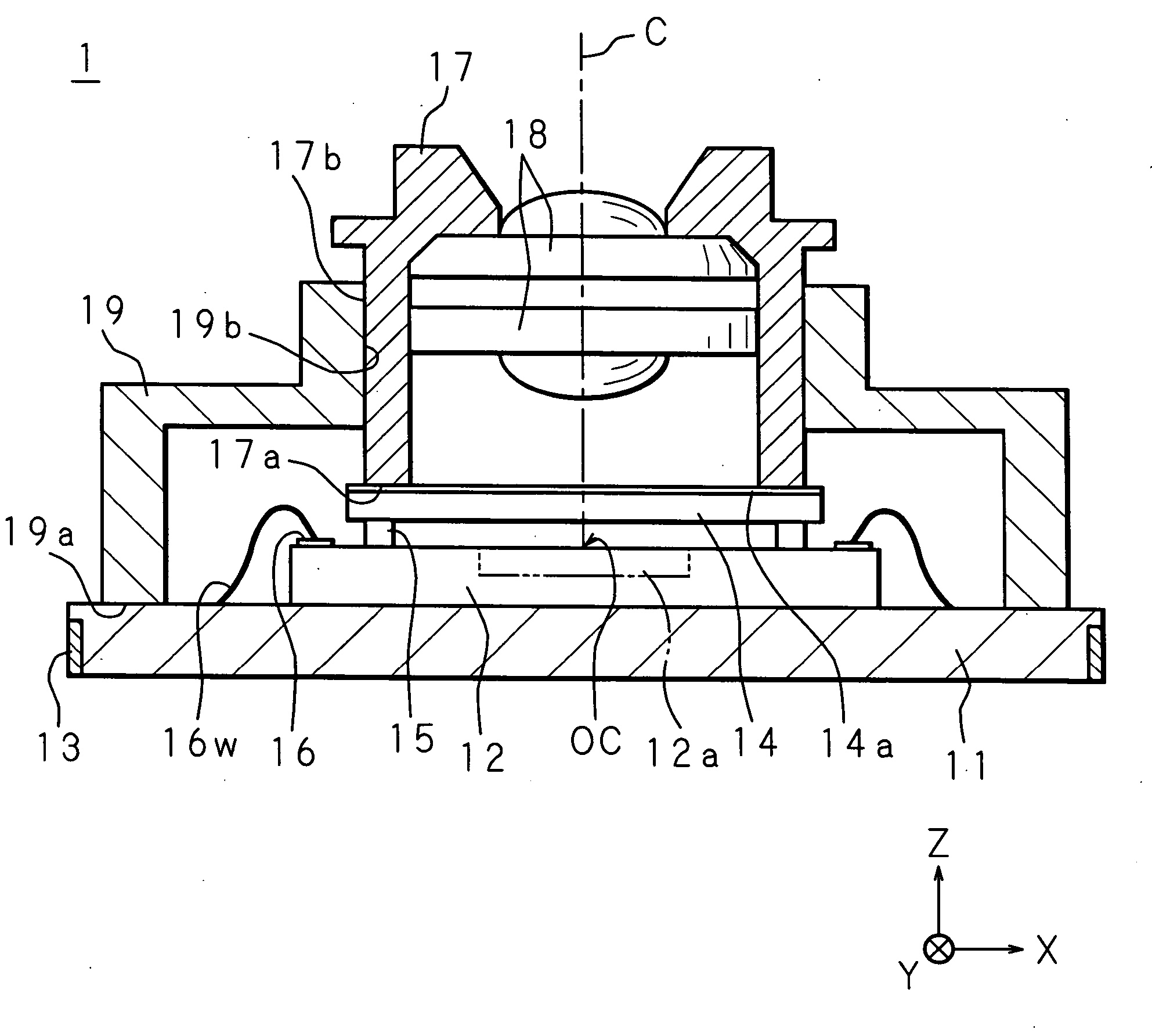
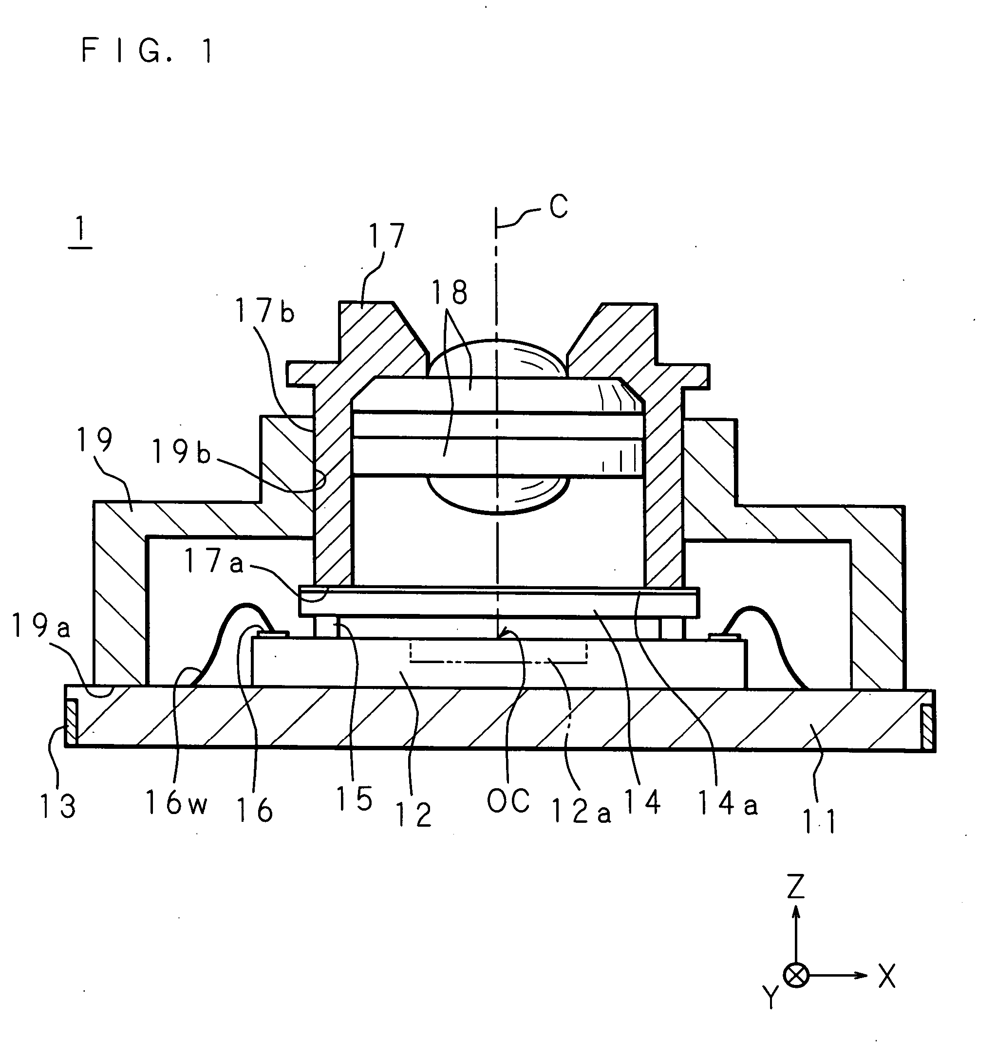
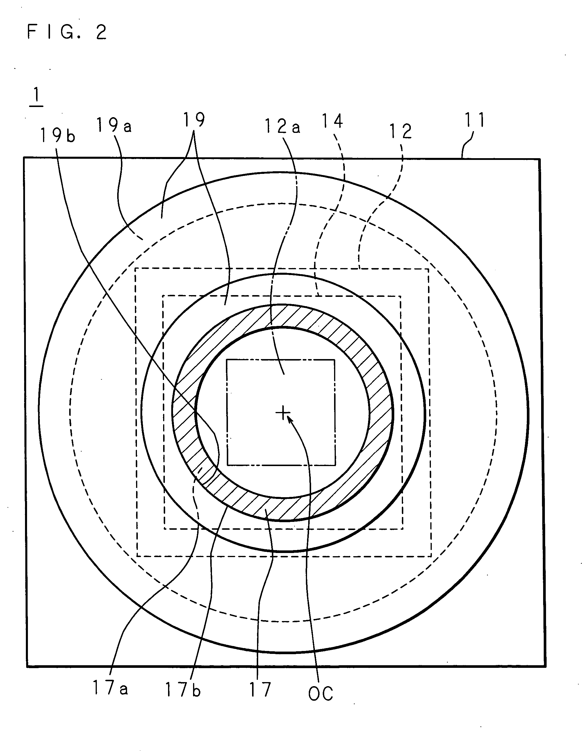
[0062]FIG. 1 is a sectional side view showing the structure of an image pickup module according to Embodiment 1 of the present invention, and FIG. 2 is a plan view of the image pickup module of Embodiment 1 of the present invention seen from a light incident side. Note that illustration of part of the components is omitted in FIG. 2 to facilitate understanding of the positional relationship among an image pickup element, a lens holder and a cover, which is a characteristic of the present invention.

[0063] In an image pickup module 1 of Embodiment 1 of the present invention, an image pickup element 12 is bonded to one surface of a substrate (base) 11 by dice bonding. The image pickup element 12 is one type of semiconductor element, such as a CCD or a CMOS imager, and comprises a light receiving section 12a in the center of a chip, and peripheral circuits, such as a read circuit for reading a signal based on the light quantity detected by the light receiving section 12a, on the periph...

embodiment 2

[0084] Although Embodiment 1 illustrates a mode in which the optical position of the lens in the XY direction and the Z direction is respectively controlled by the cover and the lens holder, it may be possible to use a lens holder that functions as a cover. Embodiment 2 illustrates an example using such a lens holder.

[0085]FIG. 7 is a sectional side view showing the structure of an image pickup module according to Embodiment 2 of the present invention.

[0086] An image pickup module 2 of Embodiment 2 of the present invention comprises a lens holder (fixing section) 27 functioning as a cover explained in Embodiment 1. A lens 28 for guiding the path of incident light to the light receiving section 12a of the image pickup element 12 is fixed on a predetermined position of the lens holder 27. The lens holder 27 has a step section 27b functioning as a contact section of the present invention, and a leg section 27a fixed (bonded) to the surface of the substrate 11 with an adhesive 63 in a...


PUM


Abstract

An image pickup module of the present invention includes a cover in the form of a tube, and a lens holder. The cover is fixed (bonded) to a base in a state in which its leg section is in contact with a surface of the base. The lens holder is inserted in an inner surface of the cover, and an outer surface of the lens holder is fixed (bonded) to the inner surface of the cover in a state in which the leg section is in contact with the transparent plate, and the outer surface is in contact with the inner surface of the cover. A lens for guiding a path of incident light to the light receiving section of the image pickup element is fixed on a predetermined position of the lens holder.

Description

CROSS-REFERENCE TO RELATED APPLICATION [0001] This non-provisional application claims priority under 35 U.S.C. §119(a) on Patent Application No. 2004-337978 filed in Japan on Nov. 22, 2004, the entire contents of which are hereby incorporated by reference. BACKGROUND OF THE INVENTION [0002] 1. Field of the Invention [0003] The present invention relates to an image pickup module comprising an image pickup element with a light receiving section, and a lens for focusing incident light on the light receiving section as a module (as a unit), and a method of manufacturing the image pickup module. [0004] 2. Description of Related Art [0005] Image pickup elements as one type of semiconductors, such as a CCD or a CMOS imager, have been used in various fields. In particular, cell phones with a camera having a camera function in addition to a communication function by installation of an image pickup element have been widely used in practical applications. With a reduction in the size, thicknes...

Claims


Application Information

Patent Timeline
IPC IPC(8): H04N5/225G02B7/02G03B11/00G03B17/02H01L27/14H01L31/02H04N5/335
CPCG02B7/02H01L27/14618H04N5/2254H01L2224/48091H01L2924/00014H04N5/2257H01L27/14632H01L27/14687H01L27/14625H04N23/57H04N23/55H01L27/146
Inventor HIROOKA, SHOHGO
Owner SHARP KK
Why Eureka
Try Eureka